For many of my applications I’m using a PWM (Pulse Width Modulated) signal. One example is the motor driver used in this project where I use one PWM signal for each motor. Another usage of PWM is to control the brightness of an LED. Processor Expert makes usage of the PWM hardware easier. Still, for some settings it is good to have the resulting signals in mind. So in this post I’m showing how the settings impact the PWM signal generated.
PWM Component
I’m using Processor Expert with CodeWarrior for MCU10.3 and the FRDM-KL25Z board for this article. As the Processor Expert PWM component is pretty much the same for all architectures and IDE’s supported, things should applicable for any other microcontroller. With MCU10.3 there is now a PWM component which makes things easy for Kinetis too:

PWM Component
💡 the only difference is that for Kinetis (ARM Cortex) and ColdFire+ there is a LDD (Logical Device Driver) component involved. While it is still possible to use the LDD driver, it is not easy to use. I use the PWM instead of the TimerUnit_LDD.
The most important settings are:
- Period: this is defines the period or frequency of the signal.
- Starting pulse width: this defines the first duty.
- Initial polarity: this determines if the duty is low or high active (see below).
Below is where the settings in the component properties I use in this example:
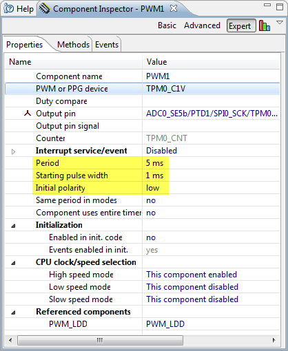
PWM settings in component
Example Code
To show things on a pin it I’m using the following code snippet:
Bit1_SetVal();
WAIT1_Waitms(1); /* 1 ms pulse on pin */
Bit1_ClrVal();

PWM1_Enable();
WAIT1_Waitms(20);
PWM1_Disable();

Bit1_SetVal();
WAIT1_Waitms(1); /* 1 ms pulse on pin */
Bit1_ClrVal();
This generates a 1 ms pulse on pin, then enables the PWM for 20 ms. I generate that 1 ms pulse so I can easily set a trigger on it with a logic analyzer.
Initial Polarity
Let’s check what the component documentation says:
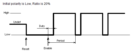
Processor Expert PWM documentation (Source: Processor Expert online help for PWM component)
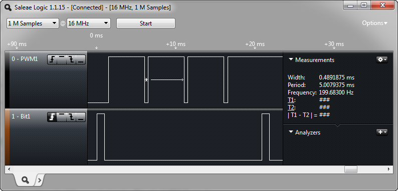
So I expect a PWM with 5 ms period: 1 ms low, then 4 ms high, and so on. Checking this with the logic analyzer confirms this:

PWM Example
The first thing to note is that the PWM remains high at the second Bit1 pulse. This because I have disabled the PWM, and it will stay in whatever state it was (high in my case).
💡 If the hardware supports it, then I can use the PWM SetValue() and ClearValue() methods to directly affect the PWM signal. This is useful if I want to disable the PWM, and have the output signal in a defined state. An even better way is to change the duty cycle in an interrupt generated by the PWM (see below).
The important thing to remember is that the initial polarity determines if the signal is ‘high’ or ‘low’ active in respect to the duty cycle.
💡 Unfortunately for the Kinetis it is not possible to change the initial polarity to ‘high’. This is possible for other microcontrollers like the S08 or ColdFire. To me, having a ‘low’ active PWM is somewhat counter-intuitive. Usually I think of “80% duty” in “the signal is 80% of the time active” while with ‘low’ polarity it is 80% low and 20% high.
Changing Duty
To change the duty cycle, several methods available:
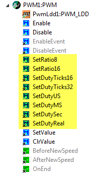
Changing Duty Methods
For example if I change it with
PWM1_SetRatio8(0xFF/10);
then I get a 10% low duty ratio for the above PWM:
10 percent low duty
Changing the duty ‘on the fly’ might have undesired effects. I recommend carefully to check what happens if the duty cycle is change inside the PWM period: depending how things are implemented in hardware and software, the new duty cycle might be effective immediately, or at the start of the next period. If the duty cycle changes within the PWM period, this might be a problem for the consumer of the signal.
Interrupts
PWM interrupts are very useful (if supported by the hardware), so I can change the duty at the right time, or do something else. In my example I want to toggle my pin. For this I enable interrupts for my PWM:

PWM Interrupts Enabled
This enables the PWM OnEnd() event method:

PWM OnEnd Event
In that event handler, I toggle my pin:
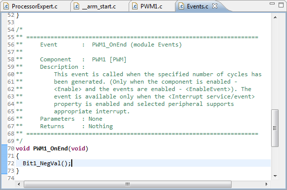
Toggling a Pin
Now my pin toggles at the end of the PWM period every 5 ms:
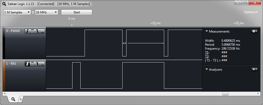
Toggling Bit1 on End of PWM Period
Summary
It is important to know that the initial polarity setting determines if the ‘active’ duty cycle is high or low. Unfortunately at least for the Kinetis KL25Z only an initial low polarity is possible. If PWM interrupts are implemented by the hardware, then this is a good place to change the duty witout impacting the PWM frequency. In any case, a logic analyzer to verify the output signal is a must in my view for every firmware and embedded developer. 🙂
Happy PWMing 🙂

Nice write up.
Do you have any idea why processor expert does not allow the user to set the starting pulse width to 0?
LikeLike
Hello,
no, this is not clear to me neither. I already have filed a ticket on this, so hopefully this gets addressed. In my view the hardware supports this (unless I’m missing something).
LikeLike
Hello,
are there any news on this issue? It still seems to exist on Processor Expert for KDS 2.0.0 RT6_b1444-1070
LikeLike
I’m using Kinetis Design Studio with Processor Expert v3.0.2 and the issue is fixed: I can specify a starting pulse of 0.
LikeLike
Hi.
Sorry to bother you, just ask a little help please I’m working with KL27Z Kinetis and took two day trying to do the same and not eh given , if you help me I appreciate it too .
LikeLike
Hi Camilo,
so what is not working? Have you tried my project with the KL25Z? The KL27Z is very different.
LikeLike
Strange that PEx doesn’t support the PWM polarity for Kinetis. If you use the Device Initialization (DI) or the Init_TPM component instead, you can set the polarity. It’s defined in ELSA and ELSB in the TPMx_CnSC register. It’s not well documented in the reference manual. Perhaps this is a PWM component oversight?
LikeLike
Hi Brad,
yes, I think this is an oversight in the PEX PWM component, and I already have filed a ticket about it.
LikeLike
Wow, thanks for the note about the KL25 supporting a high polarity PWM and the register setting for it. After some quick checking, I absolutly agree the documentation is extermly poor. I never would have realsized TPMx_CnSC register bits ELSA & ELSB control the polarity.
To easy the pain of others, you simply need to delete the or’d bit mask named TPM_CnSC_ELSA_MASK in the Timer init function for the TMPx_COSC macro to get a high polarity PWM.
LikeLike
To address the KL25 HW limitiation of not allow the programmer to set the pin level when the PWM is disabled, I found a workaround.
I created a GPIO LDD on the same pin. PE yelled at me about the pin being already in use by the timer until I learned to right-click on the pin assignment and select pin sharing.
One odd thing of note:
For the the GPIO LDD, you have to explicitly call ConnectPin() everytime the GPIO is init. I simply added the call in the init function.
LikeLike
Hi
I was wondering if TWR-KL25Z supports complementary mode? If so then what registers should I be configuring for that mode?
Danke 🙂
LikeLike
Hi,
what is this ‘complementary mode’?
Bitte 🙂
LikeLike
Complementary mode of PWM to generate two signals are inverse of each other 😀 Nevermind I found my answer! Thanks!
LikeLike
And what is the answer? I am looking for complementary mode in PE but could’t find it. Is it missing? Thanks for your help!
LikeLike
Hi !
Thanks again for the TUTO !
I’ve a problem with my code warrior, more especally with the components in PE.
For exemple i can’t do your tuto because of the methods on the compoment inspector. I do not have every generate code ! Most of the methods has the value “don’t generate code”.
Is it because I use a free codewarrior or cause i forget to install more things ?
Thanks a lot for your help !
LikeLike
Some methods could be disabled because of the component settings. If you hoover over the disabled method name, you should see an explanation and tips why it is disabled (at least most of the time). Otherwise: Let me know which methods if which component are disabled, as I’m not sure to what you refer to. If you have missed installing a component, then the component icon is grayed out. Otherwise the free CodeWarrior version only has a code size limit (at least if you are on 10.4 or 10.5), and does not impact functionality. I hope this helps?
LikeLike
Brilliant tutorial! I learned more about PE and CodeWarrior in one day reading this than in a week on my own. I do have one stupid question; since the Component Inspector has multiple pins listed for the output, which are you connecting to to view it on a scope? Could it be either?
LikeLike
That’s what tutorials are for 😉
You need to attache the scope at the pin you have selected. What is behind the pin selection is the ‘pin muxing’: in the microcontroller there is a switch to route the signals to the pin selected. So the same pin can be assigned to different internal blocks.
LikeLike
Thank you for the explanation!
If I could probe it just a little deeper: your pin selection, like mine, has several acronyms separated by backslashes. Yours says ADC0_SE5b/PTD1/SPIO_SCK/TPM… in the PWM settings in component figure. Is PTD1 then the pin to attach to the scope?
When I select PTD1 on my FRDM KE02Z, it says PTD1/KB11_P1/FTM2_CH3/SPI1_MOSI in the same location.
LikeLike
You can select the pin in the pin selection which fits best your layout on the board. And because every micrcontroller is using different pin muxing, that PTD1 pin name can be different, as other functions are possible on that pin.
LikeLike
I have a followup question regarding interrupts.
I am trying to take your update duty cycle section a step further and be able to dynamically control it via a COM port. That is, I would like to be able to enter a character in say Tera Term that will be converted to an int and passed to one of the SetDuty functions. To this end I am trying to have my interrupt poll with scanf but have so far been unsuccessful.
Is my failure so far tied to bad programming or does it go deeper (tying up the COM port for example or using the wrong function) ? Would like to hear from you on this because if I could get it running successfully, this would open an impressive range of possibilities.
Best,
Yusif Nurizade
LikeLike
What you have in mind is very well possible, and should not be hard to implement. However, do not use scanf()! Like printf(), scanf() and all the variants are evild and nasty, and cause a lot of troubles (see https://mcuoneclipse.com/2013/04/19/why-i-dont-like-printf/). Better you use for example the UTIL1_ScanDecimal8uNumber() present in the Utility component. I use these functions in my shell and in many other places.
LikeLike
Thank you for the suggestion. I actually read and now reread your blogs printf posts for this very application.
I don’t have the Utility component available in my Components Library. I followed your Why I Don’t Like printf link and saw the link to the Utility download. Is it made outside of the components already provided in CodeWarrior or am I simply not seeing it because I am using a KE02Z board? If it’s the former, I am wondering if you have a post on importing components. I’ve been unsuccessful in finding one so far.
LikeLike
I withdraw my previous query. Here is the link for anyone as foolish as me:
LikeLike
After having added the ability to turn the PWM on and off as well as modify the duty cycle via Termite, I wanted to expand to 8, ideally 16, channels. The problem I am running into is that while I know quite a few pins can support the 20 us period I need, when I add more than 3 PWM components Component Inspector begins to assign pins with overlapping timers. For example, I add PWM4 and PWM1 and PWM4 now show errors as do TU1 and TU4. Looking at the PWMs in CI, I am told the problem is in the timer unit and sure enough TU1 and TU4 now share a counter unit. Changing the output pin doesn’t do the trick, I have to actually remove one of the PWMs to get the other to clear. This is when I direct CW to add a new timing unit.
When I direct the new PWM to share a timer unit, I get an error at period for both PWMs and the TU that says “Conflict in required values from components in the project.” This happens when I set identical periods or no period at all. Have you had any experience with this? I spent quite some time on it and find myself stumped.
LikeLike
Hi Yusif,
could it be that it is this problem
thread/315129 in freescale community
?
LikeLike
I took me further to the point that I could add 8 PWM components without errors but when I tried to expand my code to cover more channels I got an explosion of errors. Post in the community for anyone that is interested:
Thanks for the suggestion,
Yusif Nurizade
LikeLike
Hi Yusif,
yes, this really looks like a bug in Processor Expert. So posting it at the Freescale forum is what I would have recommended too.
Could it be that this bug is related to this issue (thread/315129 in freescale community)?
If so, that forum post has a hot fix attached.
LikeLike
I have not used more than 2 PWM channels so far, but I think I have seen that issue you report too. It might be that using the PWM_LDD (and not using the PWM) component might help?
LikeLike
Erich,
Thank you for looking into my issue. With regard to the hot fix; I added it as per the forum suggestion. Barring the fact that I may have gotten the path wrong (C\Freescale\CW MCU v10.5\MCU\Processor Expect and dumped the appropriate files in beans and drivers) I did see improvement in that I was able to add up to 8 PWM channels as well as place more than one channel on a Timer Unit. As I recall, I was not able to do this prior to the hot fix.
I looked at PWM_LDD as you suggested but there are only 3 functions I am able to view; Init, SetDutyMs and SetRatio16. The help menu says there is a DeInit option but I am unable to see it, perhaps if I could find it, this would b worth a try, have you gotten multiple channels with PWM_LDD?
LikeLike
Hi Yusif,
I used max of two PWM channels in my projects.
LikeLike
Erich,
I saw some people below me having a somewhat similar problem so I wanted to give you an update. I fixed the issue I was having and am able to control 4+ PWM channels independently. Petr from the forums suggested disabling interrupts and that did the trick; not sure if it’s applicable in all cases but it did the trick for me.
freescale community thread/316937
LikeLike
many thanks! I think this is useful for many of us, indeed.
LikeLike
Hi, Erich!
I have a simple question related with PWM and FRDM-KL46Z. How can I control two DC motors using LM298 as driver in order to go forward and back with different speed? I think that I need 4 PWM components, but I can add only 3 because there are only 3 timers : TPM0, TPM1 and TPM2. With Processor Expert I can not add 2 PWM components having the same time counter (0 for example).
Thanks and Happy new year!
LikeLike
Hi Mihai,
I have not used the LM298. But you would need 4 PWM signals, but I think you should be able to use four channels of a single timer?
LikeLike
I do not know why I cannot use four channels of a single timer. Maybe it is a bug related with Processor Expert? I have the last version of CW10.5, downloaded from freescale.com.
LikeLike
Hi Mihai,
maybe you are seeing this bug in Processor Expert?
in freescale community thread/315129
Check out the above thread, it has a patch/fix for Processor Expert in MCU10.5
LikeLike
It seems that it is not a CW for MCU 10.5 bug. I have tested with CW for MCU 10.4 and the same problem is generated. Erich did you ever changed dynamically the channel for a PWM timer (like TPM0) ? I want to do this trick but I cannot change the channel from CH0 into CH1, for example.
Thanks again!
LikeLike
Hi Mihai,
not sure what you mean with changing dynamically the PWM timer? In my view I did: I’m changing the PWM dynamically e.g. for the DC motors of the Zumo Robots (https://mcuoneclipse.com/2013/05/30/tutorial-arduino-motorstepperservo-shield-part-1-servos/), or the PWM for dimming LEDs (https://mcuoneclipse.com/2012/12/29/pwm-and-shell-for-a-led/)
LikeLike
Hi, Erich!
I have solved my issue using two timer channels. Now, I have another question : is there a simple way to check if Bluetooth connection was lost without sending or reading messages?
Thanks for your answer!
LikeLike
Hi Mihai,
good to hear that you solved your issue. Could you post a comment how you solved it?
As for the Bluetooth: that depends on the module/firmware. Some modules/firmware use the STATE pin (see schematic on http://www.aliexpress.com/store/product/wholesale-HC-05-HC-06-Adapter-Board-for-Bluetooth-RS232-UART-Converter-Module-for-hc-05/908964_540339991.html) which tells if the module is connected or not. This usually is connected to a LED, but you can read that pin from the microcontroller too.
LikeLike
For my project I have added two timers, each of them having 2 channels enabled. Then I have created 4 PWM components : IN1, IN2, IN3 and IN4. As references IN1 and IN2 use TIMER1, IN3 and IN4 use TIMER2. My mistake was related with “Period” and “Starting pulse period” settings because initially I have set my own values (5 ms for each of them). If I use auto select option, I get “Period” equal with 3.125 ms and “Starting pulse period” equal with 3.124952, and everything it is fine.
I think that I am going to use LED pin. Thanks again!
LikeLike
Dear Erich,
First of all thank you very much for all of your tutorials they are, and have been really useful.
I am using Kinetics MK60FX512 and code warrior 10.3.
What I want to achieve is to control the speed of a fan using 3 pwm signal which will vary in speed (the duty cycle) according to the change in temperature e.g 10% increase for every degree rise in temperature. By using FTM I am using 3 channels at PTE5,PTE6 and PTE7 or my uC.
I was having problems to generate PWM since nothing was coming on the pin lets say PTE5 for channel 0 even when the PWM was enabled.
I started with you tutorial from the beginning and created PWM component. Again there are no errors etc but I can’t get any thing on the relevant pin. However, the interrupt is working fine when I am toggling a pin as you did. May be I am calling the functions for PWM wrong. e.g.,
int main() {
.
.
.
PWM_Enable(); // this should start pwm or not? should I change duty cycle before or after this
.
.
.
}
By the way, I am checking the signal through oscilloscope. It is working when the pin is toggled using interrupt so I expect I am making some mistake in software i.e. how to use pwm properly.
Regards,
Naqqash
LikeLike
Hi,
I have solved the problem of PWM. Now I am getting the signal on the relevant pin but the other problem is I can’t figure out how to change the duty cycle during ‘run time’ any suggestions?
with FTM timer I am using SeOffsetTicks(device pointer,channel,value) function but it is not working I am running into PE_ISR(Cpu_Interrupt){ PE_DEBUGHALT();} and hence no signal on the output pin. But when I use PWM_Enable() only in the main routine I am getting signals on the run time..
Regards,
Naqqash
LikeLike
Hi Naqqash,
it would be good to know which interrupt is firing. If you check https://mcuoneclipse.com/2012/02/20/oh-my-an-interrupt/ then you can enable ‘own hander for every’ then you know what is causing the interrupt?
LikeLike
Hi Erich thanks for the reply, I have tried as you suggested but got all sort of different errors. Since, the application is quite big and I am not the only one involved so I don’t want to change anything but I have seen the error messages and I know why the are coming. Nevertheless, really nice and useful idea for future.
I want to bring your attention towards the other part of my question as I said now I can enable pwm and can change its duty cycle if I change offset in the component explorer but it is only once time and remains fix for the rest of the execution of the program.
What I want is that how can I change the duty cycle during runtime. E.g. in a subroutine where I am checking the temperature value lets say if temperature is higher than 30 deg turn on the fan , now if temperature is increasing increase the speed of fan as well i.e. change the duty cycle.
Any suggestions?
Thanks
LikeLike
Hello,
you can enable the PWM with the PWM1_Enable() method (and disable it the Disable() method). The duty of the PWM can be changed with multiple functions, e.g. SetRatio8(), SetRatio16() or with the other SetDutyXX() methods.
LikeLike
Thanks a lot I was using the same function but I was using FTM timer. I don’t know why but it happened that it did not work when I used the settickoffset() function but when I used PWM component as you have already explained it worked not I can easily change my duty cycle by using one of the above mentioned funtions 🙂 thanks a lot for the help.
LikeLike
Hi me again!!
I am now running in all sort of problems when I try to use more than 1 pwm component. What I am trying to do is to use PWM1, PWM2 and PWM3 component and making FTM3 channel 0, channel 1 and channel 2 as the reference timer respectively. I have gone through some post on the freescale forum and seen your replies as well but unfortunately, my problem is still there. I have tried even using directly PWM_LDD without using pwm component directly.
The post below was useful because I managed to go through some examples provided by some members and played with them. For example the one ‘LED PWM Test’ provide by ‘Jan Rychter’ is what exactly I want but I don’t have TPM timer module I am using K60 kinetics and instead I have FTM.
freescale community thread/315129
Regards,
Naqqash
LikeLike
Fixed the problem… Strange really really Strange!!!
Since, it was just a dummy project to check the functionality I have deleted the timer and the pwm components and tried again with pwm_ldd with ftm timer and now I have no errors :O
Seems like processor expert is not that much expert after all.
LikeLike
Hi Erich,
I followed the instruction from Jonathan Campbell!
Deleting the TPM_CnSC_ELSA_MASK from TU1.c file!
However, when I build the project, the PE puts the mask back in code!
Is there any way to disable this?
Thanks
LikeLike
Nevermind!
Works fine now!
sorry for the inconvenience
LikeLike
You can disable code generation for a module: https://mcuoneclipse.com/2012/03/23/disable-my-code-generation/
LikeLike
I did the same as shown in the tutorial but not able to get the expected output. 😦
LikeLike
What output do you get?
LikeLike
Hi! Is there any way to generate interrupt on rising/falling edge inside period instead on end of period?
LikeLike
Hi Seba,
that depends on the device you are using: some devices do support this, others not.
LikeLike
Hi!
I would like generate one 1:1 signal (50% duty) with variable period with CodeWarrior for MCU 10.6. I’ve tried many beans (timerOut, timerInt…) with PE, but I never have methods to change in runtime the period. It should be very easy (I just want to generate pulses, regardless the duration) with variable frecuency (having methods to change in any time). A always have “Inherited component does not support this feature: Runtime setting type interval”. Do you know how to resolve it?
LikeLike
I have to say I have other Timers generating PWM without problems, and I would like to use one Timer not shared with others…
LikeLike
Hi Pablo,
are you using the PPG component?
LikeLike
Hi!
Ok, I’ve tried to use PPG and, using interval values on timer, PE seems to not show any error. Also, I have enabled functions to change period, that was I wanted!.
I will check codeGeneration this evening or tomorrow, but I suppose it is resolved. Thanks!
LikeLike
Hi,
I would like to start PWM in interrupt from some timer. I use PWM component with Code Warrior 10.6 with MCF51MM256CLK mcu. Problem is that first period (or starting pulse width, i use low initial polarity) of PWM always has wrong time, almost always shorter than setted. I thing there is maybe something wrong with timer used by PWM component. Could you propose some solution?
LikeLike
Hi seba,
this sounds like the timer is already running, causing that glitch. Have you reset the timer counter register before starting the PWM?
LikeLike
Hi Erich,
No, I didn’t reset timer counter register before starting PWM. Now it is working. Thank You for help. But I wonder why timer was running, I didn’t start it, Enable PWM was the first use of this.
Problem disclose when there is two or more PWM components in project (even not used now) which use the same timer. If there is one PWM component then everything is ok (without reset counter) and PWM starts in right time.
LikeLike
Are the two PWM’s using a shared timer module?
LikeLike
Yes, PWMs are using two channels o one timer module, I should add this. If PWMs are using different timer modules everything is ok.
LikeLike
Hi,
I would like to do two pwm’s on the kl46z. However, I’m getting some erros:
“Error in the inherited component settings (PWM_LDD)”.
I’m using processor expert on kinetis design studio. I just added 2 PWM components but I can’t fix those problems.
Can someone help me? (I’ve read comments here, but it didn’t work.)
Thank you.
LikeLike
Hello,
probably the PWM_LDD settings of your PWM components have a conflict.
You need to ‘unzoom’ the PWM component to check the ‘PWM_LDD’ subcomponent settings.
If you are using the same PWM (FTM) device, you need to make sure that the base frequency is the same, otherwise the PWM_LDD component will flag the error.
Example:
PWM0 -> uses FTM0_C3V, 100 kHz period, subcomponent PWM_LDD references MOTTU TimerUnit_LDD
PWM1 -> uses FTM0_C2V, 100 kHz period, subcomponent PWM_LDD references MOTTU TimerUnit_LDD
MUTTU -> FTM0, 2 channels in the channel list: FTM0_C3V and FTM3_C2V
In essense. you need to make sure that your TimerUnit_LDD is matching the PWM components you are using. The PWM components have a PWM_LDD subcomponent which use a ‘shared’ TimerUnit_LDD. That shared TimerUnit_LDD needs to be aligned to the PWM components you are using.
I hope this helps.
Erich
LikeLike
I got it.
Thank you so much.
LikeLike
Hello Prof. Styger,
please can you tell me how to calculate minimum amd maximum value of PWM or Duty Cycle i can generate with KEA8 Coretx M0+ controller with the folliwng data
20 Mhz Internal Oscillator
16 Bit Timer
128 Prescale
Thank you
Kind Regradrs,
Robin
LikeLike
Hi Robin,
the minimal PWM duty cycle will be one tick of your clock after the prescaler you have setup.
If you go to the timing dialog in Processor Expert, you get that information as well.
I hope this helps,
Erich
LikeLike
Hallo Herr Styger,
Danke schön.
MFG,
Robin
LikeLike
thats great…!!!
LikeLike
Hi Erich,
As always a great great tutorial.
I am working with the KL25 on KDS 3.0.0 and PE.
I followed the tutorial and managed to define a PWM for pin PTD4. I am trying to do it also for pin PTA1 and I am not able to. I defined it as so:
device: TPM2_C0V
output pin: PTA1
Period: 21.845333 ms
starting pulse width 10.922667
Initial polarity: low
Enabled in init. code: yes
and I use the enable and disable to turn PWM on/off.
In addition I share the PTA1 pin with a BitIO component as described by Jonathan Campbell.
when using the BitIO set/clr val functions the pin responds, so I assume that the HW is configured right.
LikeLike
Hi Avner,
I have not tried your setup, but my thinking is that the pin sharing alone will not change the muxing. I think you need to make sure that if you switch from BitIO to PWM properly. I assume that in ‘PWM only’ the pin is working properly too?
LikeLike
Hi Erich,
Thanks for the reply!! 🙂
I was able to solve it. it turn out that when using both PWM and BitIO components with pin sharing, you should define the PWM first and then the BitIO. otherwise it would not work….
Thanks again for this tutorial! it helped me so much!
Avner
LikeLike
I would hook up a logic analyzer to all signals, especially as well the IRQ line. Maybe you find nRF module which is able to send, and then hopefully your module receives something.
Otherwise you need some $20k equipment to see what is transmitted over the air (RF network analyzer) 😦
LikeLike
Hi Erich,
I do as per your procedures to control the brightness of an LED. But the LED is just blinking when I use the EVENTS.C
unsigned ratio = 0;
void PWM1_OnEnd(void)
{
PWM1_SetRatio16(++ratio); //change duty
}
in FRDM-KL05Z instead of your code:
Bit1_SetVal();
WAIT1_Waitms(1); /* 1 ms pulse on pin */
Bit1_ClrVal();
PWM1_Enable();
WAIT1_Waitms(20);
PWM1_Disable();
Bit1_SetVal();
WAIT1_Waitms(1); /* 1 ms pulse on pin */
Bit1_ClrVal();
Because when I try generate the code for SetVal() and ClrVal() there is error(Inherited component doesn’t support this feature). I selected the TPM0_C3V of pin ADC0_SE11/PTB8/TPM0_CH3.I enabled the interrupt in PWM.I just used the PWM component only. The pin ADC0_SE11/PTB8/TPM0_CH3 is the green LED in the FRDM-KL05Z. Please help on this. I want control the brightness of the led.
LikeLike
Check that the ClrVal() and SetVal() methods are enabled in your component (see “Toggle Enable/Disable” in https://mcuoneclipse.com/2012/03/09/quickstart-for-processor-expert-in-eclipse/). Other than that, this article might be helpful too: https://mcuoneclipse.com/2013/03/16/pwm-for-processor-expert-explained/
I hope this helps,
Erich
LikeLike
Thanks for this post, bumped on it trying to adjust the frequency of a phone vibrator motor using PTA1 of FRDM-K64F, now I understand the active low signal implications to the inverse duty cycle. This is helpful to sort things out. Luckily by now the component settings are fixed in PE and I just set active high.
LikeLike
Hi Erich! Thanks for share your knowledge with us, I would like ask you where I can find a detailed explanation of TimerUnits and PWM. In my project I need use 4 speed’s motors control on my project with kl46z and I have a nightmare trying diferents combinations, and I am sure the best way to do this is learning and have a deep understanding of TimerUnits and PWM. Thanks!
LikeLike
Hi Carlos,
I would recommend to have a look at the FTM (FlexTimer Module) in the reference manual of your device.
LikeLike
Thank you!
LikeLike
Hi Erich,
I am facing a issue : PWM driven LED is not getting OFF during PWM signals ON time.
I am driving (blinking) a LED by PWM signal generated by Processor Experts PWM_LDD component for microcontroller MK10DN512VLQ10. PWM_LDD use FTM0_MOD as period device and FTM0_C7V as duty device.
LED is connected as common cathode and anode is driven by microcontrollers pin PTD7.
PWM signal properties are : Total period = 1 Sec , ON time = 50mS and initial polarity is high.
In firmware , LED is turned ON by PWM_Enable() function and turned OFF by PWM_Disable() function.
If LED turned OFF during 50mS ON period of PWM signal , LED still remain ON but with very low intensity .LED becomes OFF after some time (random time) .
On Oscilloscope ,it is observed that the pin PTD7 remains high for some random time and then becomes low. During this period LED remains ON with low intensity.
I tried by clearing the pin PTD7 after calling PWM_Disable() function. Also , tried by making duty cycle 0 after calling PWM_Disable() to turn the PTD7 to low . No improvement seen.
It seems that function PWM_Disable() stops PWM module but dont clear the pin PTD7 if PWM is disabled during PWM signal ON time
.
Please let me know your thought on this.
LikeLike
I have not tried this on the K10, but I think it should be the same for all Kinetis: The Enable() function basically turns off the input clock/prescaler of the TPM pin. So the output pin should still drive the last (high or low) value. As you said, I would call SetValue() or ClrValue() to set the pin high or low (depending on your needs) after disabling the TPM.
LikeLike
Hello Erich,
Thank you for reply. Calling SetValue() or ClrValue() after disabling TPM actually changes the polarity. It doesn’t clear the pin.
BR,
Rohit
LikeLike
Hi Rohit,
that might be K10 specific. I know that not all Kinetis allow to set the pin logic if in PWM mode. You would have to re-configure it as output pin first.
Erich
LikeLike
Hi Erich, is there anything like a Programmable Pulse Generator component available within PE or do you know of any plans for something like this? I want to generate a number of pulses at regular intervals (ideally, with varying frequency too) based on values from a look-up table. I can’t think of a suitable way to do this using PE – maybe software PWM would be the way to go
LikeLike
Hi Kevin,
there is the PPG (Programmable Pulse Generator) component, but its availability depends on the device used.
You might have a look at using DMA as well. Have a look at
where I use it to generate special pulse sequences with minimal CPU load.
LikeLike
Hello Erich,
I saw you mention the PPG component in a few posts on the NXP forum, and am attempting to use it in a k64f project. My requirements list a need to configure an array of PWM outputs to a run-time configurable frequency. The PPG component appears to allow me to do this, but it doesn’t share the Flextimers well. is there any way to configure the PPG’s to work in parallel? so to speak using a shared but changeable frequency and distinct duty cycles for each channel? In this case, I’m using FTM0. my test program is just attempting to set both PPG’s to FTM0_C1 and FTM0_C2 respectively, but Codewarrior wont allow them to share the Period parameter. Any help is appreciated.
-Best Regards
Nate
LikeLike
Hi Nate,
you could use the normal (timer) component, and then use the PDD macros (https://mcuoneclipse.com/2013/05/11/low-level-coding-with-pdd-physical-device-driver/) for things like changing the period register of each channel? Basically using PDD as a way to access the low level functions you need?
LikeLike
Hi Erich
Thank you very much for your clear clarification for this application, I am using Kinetis Design Studio Version: 3.2.0 to program an FRM-KL02Z. I have following errors after debugging:
C:\../Sources/main.c:59: undefined reference to `Bit1_ClrVal’
C:\../Sources/main.c:61: undefined reference to `PWM1_Enable’
C:\../Sources/main.c:62: undefined reference to `WAIT1_Waitms’
C:\../Sources/main.c:63: undefined reference to `PWM1_Disable’
C:\../Sources/main.c:65: undefined reference to `Bit1_SetVal’
C:\../Sources/main.c:66: undefined reference to `WAIT1_Waitms’
C:\../Sources/main.c:67: undefined reference to `Bit1_ClrVal’
May I have your help please to fix this problem 🙂
Best Regards
Banu
LikeLike
It seems to me that you have not generated Processor Expert code? These files will be placed into the Generated_Code folder once you have generated them.
LikeLike
Hi Erich
I generated a Processor Expert code, Following errors are still available:
C:\../Sources/main.c:61: undefined reference to `PWM1_Enable’
C:\../Sources/main.c:63: undefined reference to `PWM1_Disable’
In Generated_Code folder there are following related files:
PWM1.c
PWM1.h
May I have your help please to fix this problem 🙂
Best Regards
Banu
LikeLike
Hi Banu,
you have to turn on these functions. Unfold that PWM component and use the context menu to enable the method Enable() and Disable(). See as well https://mcuoneclipse.com/2012/03/23/disable-my-code-generation/
I hope this helps,
Erich
LikeLiked by 1 person
How would this translate to a FlexPWM set up? I am using the the MC56F82748VLH and I would like to use the eFlexPWM with phase shifting.
LikeLike
I’m not sure how similar the eFlexPWM for that DSC microcontroller is. But if you have a Processor Expert component for it, I think it should be very similar?
LikeLike
There is only a eFlexPWM_Init component, which does not seem to do anything: oscilloscope cannot detect a pulse. Ended up hand-coding the initialization.
LikeLike
Hi Erich. Is it possible to copy the signal from a pwm component to a bitIO?
LikeLike
not sure what you mean with this? The PWM signal can only be put on a single pin, so you cannot ‘copy’ it to another pin. Or can you detail what you mean with this?
LikeLike
I have two leds in my project. LED 1 is set to pwm, where I can change its intensity from 0 to 100%. LED 2 is set to bitIO, where I can just turn it on and off. Is it possible to oscillate LED 2 to match the signal pwm of LED 1? What is the best way to do this?
LikeLike
what about configure the PWM to use interrupts and use that to toggle LED2? You need to be a bit careful about interrupt load, but that’s an easy way.
The other way would be to use DMA for the PWM and add a second DMA channel to toggle the LED2, but that’s more complex to set up.
LikeLike
By activating the pwm interrupts, should I invert LED 2 in the OnEnd event?
LikeLike
Yes, that’s how I would do it.
LikeLike