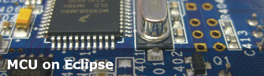
I’m working now on a lecture robot project using my Freedom Board. And for this I need a wireless communication. I already have IEEE802.15.4 (SMAC) working, but I wanted to add Bluetooth as a low-cost option. I have found an inexpensive Bluetooth module which is available for only around $4-8 which we use in another university class project. The module is an AT command module: that means the microcontroller communicates with AT serial commands with the module, and the Bluetooth stack itself runs on the module. In a minimal configuration I only need 3.3V, GND, TX and RX plus a CMD (Command) pin:

Bluetooth Module
I have found several sources (wavesen.com, suntekstore.com, e-gizmo.com, dx.com) selling that module. Browsing the web shows other sources, although sometimes it is hard to tell which module they are using. I have found one at Seedstudio, but not sure if this is the same, as they hide the module used with metal shielding.
💡 Google for “HC-05 Bluetooth” and plenty of links will show up. The module I use is known as “BT400_B6” too.
There are several variants of this module available:
- Industrial level: HC-03, HC-04-M and HC-04-S
- Consumer level: HC-05, HC06-M, HC06-S
I’m using the HC-05 which supports switching between master and slave mode. The HC-06 cannot switch between master and slave mode.
Usage of the module is very simple: out of the box I can connect to the module using a virtual COM port, and start sending/receiving UART commands.
To for early test connections, I have soldered connectors to the board:

Soldered Connectors
That way I can easily connect it to any pins on the Freedom board:

Bluetooth Module Connected to the Freedom Board
That’s of course only a temporary solution: I have created an adapter print in Eagle which takes advantage of the other pins of the module (status LED’s and I/O pins):

Bluetooth Adapter Schematic

Eagle Board Layout
Rev 0.1 of the board is in production now. If everything works out, then I’ll have a good adapter board I can use for many projects. A board layout for the Freedom board as ‘Arduino’ extension board is in the works too.
Processor Expert Bluetooth Component
To simplify usage of the module, I have created a Processor Expert Bluetooth component. It has methods for all the AT commands:

Bluetooth_EGBT Component Methods
In the properties the Serial interface plus the optional CMD (Command) pin is configured:

Bluetooth Component Properties
The component help comes with links to vendors, and has all the important data sheets included :-):

Driver Documentation
It features a shell (command line) interface which makes usage and configuration really easy:

Freedom Bluetooth Shell
The status command retrieves information from the module:

Bluetooth Status
In addition to using the component methods, it features to send any AT commands directly:

AT Commands
Once connected, commands can be sent to the other side using the ‘send’ command. And commands sent from the connected device are parsed by the shell.
In the example below I’m connected over the Bluetooth bridge to the Freedom board and can turn on/off/etc the LED’s on the board:

Remote Bluetooth Connection
Example Project
An example project and Processor Expert components are available on GitHub. The Project is using multiple Processor Expert projects:

Bluetooth Project
The project features a shell and serial bridge over UART. That way a notebook can communicate with the board over bluetooth as it would be locally connected. The software really only takes a few lines of code in Shell.c:
/** * \file * \brief This is the implementation module for the shell * * This interface file is used for a console and terminal. * That way we can interact with the target and change settings using a shell implementation. */ #include "Shell.h" #include "CLS1.h" #include "LEDR.h" #include "LEDG.h" #include "LEDB.h" #include "BT1.h" static const CLS1_ParseCommandCallback CmdParserTable[] = { CLS1_ParseCommand, #if LEDR_PARSE_COMMAND_ENABLED LEDR_ParseCommand, #endif #if LEDG_PARSE_COMMAND_ENABLED LEDG_ParseCommand, #endif #if LEDB_PARSE_COMMAND_ENABLED LEDB_ParseCommand, #endif #if BT1_PARSE_COMMAND_ENABLED BT1_ParseCommand, #endif NULL /* sentinel */ }; /* Bluetooth stdio */ static CLS1_ConstStdIOType BT_stdio = { (CLS1_StdIO_In_FctType)BT1_StdIOReadChar, /* stdin */ (CLS1_StdIO_OutErr_FctType)BT1_StdIOSendChar, /* stdout */ (CLS1_StdIO_OutErr_FctType)BT1_StdIOSendChar, /* stderr */ BT1_StdIOKeyPressed /* if input is not empty */ }; void SHELL_Run(void) { unsigned char buf[32]; unsigned char bTbuf[32]; buf[0]='\0'; bTbuf[0]='\0'; CLS1_ParseWithCommandTable((unsigned char*)CLS1_CMD_HELP, CLS1_GetStdio(), CmdParserTable); for(;;) { (void)CLS1_ReadAndParseWithCommandTable(buf, sizeof(buf), CLS1_GetStdio(), CmdParserTable); (void)CLS1_ReadAndParseWithCommandTable(bTbuf, sizeof(bTbuf), &BT_stdio, CmdParserTable); } }CmdParserTable[] is a table of more command line parsers, terminated with a NULL entry. BT_stdio is an extra standard I/O structure used for the Bluetooth serial bridge. SHELL_Run() reads and writes both to the onboard serial (OpenSDA USB CDC) channel and to the Bluetooth bridge. As the LEDs come with a command line interface, I can turn the LEDs on and off from a remote notebook over the Bluetooth bridge :mgreen:.
DealExtreme Bluetooth Modules
I ordered some inexpensive modules from DealExtreme (DX). The work, but are slave mode only. And seems that they have a different firmware (Linvor 1.5) on it. I have not done it myself, but this post explains the differences between Linvor and HC05 firmware, and how to program the firmware to the HC05 one :-). The only schematics for this module I have found AliExpress.
Summary
With this HC-05 Bluetooth module I have an easy an inexpensive way to add bluetooth connectivity to my projects. With the adapter PCB I will be able to easily interface it with most of my boards. And having a Processor Expert component makes using it trivial :-).
Happy Toothing 🙂

Thank you!
LikeLike
Hi again!
Erich, where is the Bluetooth_EGBT component located? I was looking for the .PEupd files all over Github.
Cristian
LikeLike
I have not created such a .PEupd file (would be additional work). The component sources are here: https://github.com/ErichStyger/mcuoneclipse
The advantage (or disadvantage) is that you can get everything, with all the components I have created :-). All what you need is to place the ‘Beans’ and ‘Drivers’ folder into your Processor Expert ‘working’ folder (which is for me C:\ProgramData\Processor Expert\CWMCU_PE5_00). If this does not work for you, let me know, and I create a .PEupd file.
LikeLike
It worked!
Have I missed some lessons? 🙂 Can you explain what is going on with the Beans and Drivers? The last time I remember I was still downloading and using the .PEupd files.
Also, maybe you have some time to post a tutorial on how to use this Github thing.
Thanks!
Cristian
LikeLike
Hi Cristian,
.PEupd files are created when you export a component. Basically it packages all the files. That’s ok for a single component. But if you have (as I have) more than 100 components, sharing updates is very time consuming. So I shared on GitHub my components (well, nearly all, because for some I do not have distribution rights). So the files on GitHub are the same, but the latest and greatest, and you see all the changes/etc. And everyone can fork and help contributing/fixing/changing/extending. GitHub is not much differnt from any version control system. But I plan to describe how to use EGit: that’s an excellent Git plugin for Eclipse. Beside of this I use TortoiseGit. There are plenty of tutorial available for it on the net.
LikeLike
I have had good luck with similar Bluetooth modules pre-attached to a little carrier board.
Like ebay # 400413829836 (I have not specifically bought from that seller) There must be 100 ebay sellers in China selling boards similar to these. I selected mine based on lowest price compared to quickest postage.
They are a little tricky to set the name and baudrate. Very sensitive to the rate at which the AT commands are sent. And I replaced the right angle header (which results in pins sticking straight out the end of the module) with straight pins (so the module can plug into another PCB and lay flat.
LikeLike
Yes, it seems many variants of these modules are around (which is good). I have found out that the reset/boot time of these modules can be tricky to handle: sometimes it takes up to a minute until the module is up and running. I think it would be possible to connect to the two output status LED pins and then poll the pin status to find out the status of the module. But that sounds not easy too. So what I typically do is sending AT commands to the module, and then see if it responds.
LikeLike
I really like the Bluetooth as a connection for “printf debugging”.
The Bluetooth stays connected to Windows as long as the power is on. So I can reflash and reboot the micros as many times as I want and not have to fiddle with restarting USB, etc. Only if I power down do I have to restart the Windows side terminal program.
These Chinese clones are far cheaper too than buying the RN-41 modules from normal suppliers or buying the modules from SparkFun, etc.
LikeLike
Yes, they are incredibly inexpensive. I like the connectivity for running a simply shell/command line interface on my boards, so I can send commands/inspect the status/etc. I only have found out that some DELL machines with their built-in Bluetooth modules seem to have sometimes issues to connect. Using a cheap USB Bluetooth module works.
LikeLike
Yup, I am using Mini USB Bluetooth Dongle (I bought 4 of them) on desktop and laptop because none of my PCs have bluetooth built-in. I paid only US $0.99 including the postage for the gadgets.
LikeLike
Hi!
I need some more help with this tutorial. I have problems with the LED components: The LED components included in your Freedom_Blue have the ParseCommand enabled, but if I place a new LED from the components library it has the ParseCommand method disabled and I can’t enable it. How can I enable it?
Cristian
LikeLike
Hi Cristian,
I assume you have the components from https://github.com/ErichStyger/mcuoneclipse.
To have the ParseCommand() method enabled, you need to have the ‘Shell’ option enabled in the LED properties.
There you ‘link’ to the shell and utility component.
The method ParseCommand() is enabled/disabled depending if you have the shell enabled in the properties or not.
I add a note to the method properties/tool tip help to make this more clear.
LikeLike
Just, downloaded the latest versions from github. I can now enable/disable the ParseCommand method of the LED components.
Now, I want to add duty to the LED in addition to the on/off commands like it was in the old Freedom_Shell example. Which are the steps for it?
Cristian
LikeLike
Hi Cristian,
in the LED properties, disable the ‘On/Off’ and enable the ‘PWM’ setting.
In the PWM sub-component, go to the PWM_LDD subcomponent and add a linked component (under ‘Referenced component’) to create a shared TimerUnit_LDD.
Then configure on the PWM subcomponent things like pin, period, starting pulse width.
LikeLike
Yess! It works! 🙂
Thanks
LikeLike
You are welcome 🙂 And there is always Flattr 😉
LikeLike
I checked what Flattr is about and I am ready to start rewarding your help. It is not clear how the money will reach you because Flattr seems to be a common fund for creators with no specific targeted creator. Maybe you post some clear instructions for it.
However, I was thinking of proposing you a collaboration in a project involving development of an educational tool: some sort of universal data acquisition and logging module for Physics experiments(electricity, light, sound, environment, etc).
This small FRDM Kl25Z seems perfect for this job, and thanks to your tutorials I am advancing fast and I am sure I will use it as the base for the universal module.
The project I am talking about will be addressed to primary school up to high school children. It is already approved and funded by our government and I can pay consultancy, materials and wages. (It is similar to FP7 European projects but smaller – at a national scale). If you are interested -and available :), I can provide more technical aspects.
Cristian
office@computerpower.ro
LikeLike
Hi Cristian,
I have been asked by others if I could add some kind of way for appreciation. Flattr is exactly used for something like this: I have a monthly amount (e.g. 5 Euro) I want to flattr, and while browsing the web, I can reward and ‘flattr’ content. At the end of the month, my flattr budget will be distributed among all the ones I have flattred: If I flattr one thing, it gets the amount. If I flattr hundred things, then everyone gets 1/100 of the amount. I simply use it to show appreciation to any useful content I see (and which of course have flattr enabled). For example many GitHub respositories are ‘flattrable’, and it is my way to show others that I like their content (apart of pressing the ‘like it’ button :-).
But don’t feel obliged to use something like this. I’m doing this blog for fun. Because I’m learning new things, and it is rewarding to see that others can use it, and create useful things out of it. Like yourself using this stuff for primiary school and high school children. This is enough reward for me!
I checked out your web site: very interesting. And it helped me again to refresh my knowledge in Romanian (I definitely miss Buchuresti!).
Multumesc mult,
Erich
LikeLike
Well, your answer encourages me to think about a serious collaboration.
I couldn’t see no Flattr directions in your blog pages.
Bucuresti are nevoie si te asteapta din nou.
Cristian
LikeLike
If you configure it for PWM, and have the shell interface enabled, then the component will automatically generate the code for the ‘duty’ command. It’s all implemented in the LED component itself. I have configured the red LED of the Freedom_Blue project to use PWM and pushed that updated project to the GitHub.
LikeLike
I want to add a duty command in command parser LEDR_ParseCommand() like this:
else if (UTIL1_strcmp((char*)cmd, “LEDR duty”)==0) {
*handled = TRUE;
LEDR_SetRatio16(1000);
return ERR_OK;
but it it erased when building the project. Where can I add this extra command?
LikeLike
Pingback: Be Aware of the Baud Problem | MCU on Eclipse
I was curious about the HV-05 you’re using.
Do you know if through the AT commands (or perhaps other pins) it would be possible to turn on / off the visibility?
for example build up a device and initially let it pair up with a phone/computer etc.
But then always stay associated with that paired device until someone hits a “pair with new device” or “add a new device” switch?
LikeLike
I have added the data sheets I had found to the GitHub with all the components (hhttps://github.com/ErichStyger/McuOnEclipse_PEx).
I have not used it in that way you are suggesting. But I see that it is possible to maintain a list of authenticated devices. Have a look at AT+RMSAD or AT+INQC, AT+PAIR. With AT+PAIR and AT+LINK you can connect to a specific device.
LikeLike
Pingback: Pololu Line Following Robot with Freedom Board | MCU on Eclipse
Pingback: Freedom Track Robot with IEEE802.15.4/SMAC | MCU on Eclipse
Eric, great work, I’m a big fan! Do you know or can you point me to some resources on what it takes to get these modules to pair with and be a data communication interface to an android or i-phone?
LikeLike
Hi Victor,
Thanks 🙂
what would be needed is that the iPhone or Android phone would offer a virtual COM port. I tried to search something for iPhone, but failed. It looks like this is not possible or offered as an app. So would love to see a solution, but have not found one.
LikeLike
Hi Victor,
I might have found something for you how to attach to the module with Android:
“Once power was applied I used a Bluetooth equipped Android tablet (and later my Android phone) to attach to the boards. Their default names were all “linvor” and each was found without any trouble. On the Android devices I used a terminal program called Blue Term to attach to them. Unfortunately there is nothing that you can do beyond attaching unless something is attached to the serial port on the module.”
Source: http://trainelectronics.com/Bluetooth/
LikeLike
This is very interesting to me, too. For one of my projects I’m considering buying an Android tablet to play with. If I can’t bluetooth to my micros, there’s no reason to bother. …/Bill
LikeLike
Hi, I want to know how to download the components for bluetooth, as I download it?
LikeLike
Hello,
you can download and install the components from GitHub, see
As for the bluetooth device: Just want to let you know that I’m working on an article to support the HC-06 module. This article is using the HC-05 module which has more capabilities.
LikeLike
Hi erich!
I am a beginner and I bought a kl25z and hc-05 and want to put it to work but do not know how to download the file. PEupd to configure the bluetooth, you can help with that as only turn the LED and use the pwm?
LikeLike
Hello Rancell,
about using LED with PWM, see https://mcuoneclipse.com/2012/12/29/pwm-and-shell-for-a-led/
For how to download a file with the debugger or MSD bootoloader, see https://mcuoneclipse.com/2012/09/20/opensda-on-the-freedom-kl25z-board/
I hope this helps.
LikeLike
Could you send me the files you used in this project, or can you tell me the address where to download than http://steinerberg.com/EmbeddedComponents/ that are not there.
LikeLike
Hi Rancell,
everything is on GitHub now.
The project is here:
https://github.com/ErichStyger/mcuoneclipse/tree/master/Examples/CodeWarrior/FRDM-KL25Z/Freedom_Blue
How to get the components is described here:
I hope this helps.
LikeLike
Hey Erich,I’ve made some progress using your BT component. It looks as though I’m communicating with the module in the shell in that it responds to the ‘status’ command and reports a lot of information that looks reasonable. My Windows 7 computer also recognizes the device. But it seems to kind of crash the processor when I do a “send.” Must be something I’m doing wrong on the Windows side because I paired it with my phone and connected to it using BlueTerm app and then the send command worked, but I think it took it out of AT command mode when I paired it with the phone? When I shut BT off on my phone it responded to the AT commands through the shell again (no ERRORs). Can you shed any light on any of this? I guess the good news is it seems clear that it’s *possible* to get data to/from a phone using the HC-05 module.
LikeLike
I was able to send data to my computer terminal as well after posting earlier. For some reason it seems like the module shows up as two serial ports on my computer and I had connected to the wrong one, which I guess was causing it to crash somehow? Still curious about the behavior that it seems to go into transparent mode when it’s paired with a host, is that normal? The other question I had was what you think about adding some kind of “receive” function to the shell so you can test communication from the PC to the MCU over bluetooth as well? Or perhaps that is what you are doing with the CSL1 component in your example at the end of the post? I have to admit that went slightly over my head.
LikeLike
Hi Victor,
yes, I have two serial ports as well, and only one it usable (the other blocks on my system, and I have to kill my terminal). Check the device manager which device is the active one (Devices and Printers > right click on bluetooth device > Hardware, and here you should see which port it is using).
And yes, the Freedom_Blue project is using the CLS1 component to bridge with the bluetooth module. It is using re-mapped stdio for this:
/* Bluetooth stdio */
static CLS1_ConstStdIOType BT_stdio = {
(CLS1_StdIO_In_FctType)BT1_StdIOReadChar, /* stdin */
(CLS1_StdIO_OutErr_FctType)BT1_StdIOSendChar, /* stdout */
(CLS1_StdIO_OutErr_FctType)BT1_StdIOSendChar, /* stderr */
BT1_StdIOKeyPressed /* if input is not empty */
};
With this, I can send/receive from the module.
I hope this helps.
LikeLike
Hi Victor,
as soon as the module is paired up, you cannot send AT commands any more. The AT commands will be sent to the other side of the bridge (e.g. the terminal windows on the host) as normal text. That’s why if you shut off your phone, it will again respond to your AT commands, as the devices are not connected.
The CMD pin is supposed to swithc the module back to AT command mode, altough I have not tested it out fully. I believe that pin is only used during reset of the module. I’m working right now on a HC-06 module, and things are different here again 😦
LikeLike
Pingback: Using the HC-06 Bluetooth Module | MCU on Eclipse
Have you tried to pair HC-06 with different mobile phones? I am using Seeedstudio one but not able to see it in My HTC Inspire. While it’s working fine with other mobile.
Any idea or is there any limitation with HC-06 or HC-05 ?
LikeLike
I have no Android phone, so I cannot tell. The HC-06 or HC-05 should not have a limitation in this respect. It is just that the HC-06 has limited API commands, and only can be a device (no host). You need a proper Bluetooth SPP implementation.
You might check this post and comments too: https://mcuoneclipse.com/2013/06/19/using-the-hc-06-bluetooth-module/
LikeLike
It seems like there are build-dependency issues somewhere with the BluetoothEGBT Processor Expert component if you don’t enable the shell interface at the component level. Specifically I get a number of errors in the generated BT1 files about size_t not being understood. All the errors go away if I enable the shell, choose FSShell, and just leave the shell interface disabld in the FSShell referenced component. Am I missing something?
LikeLike
Hi Victor,
for size_t I need to include . As checked BT1.h, and this header file uses size_t, but does not include that file in its header. So I think this is the problem you are seeing. I don’t have the probelm probably because somewhere else (before including BT1.h I have stddef.h included. I’ll add now to BT1.h so this problem should go away. Can you try this on your end if this fixes the problem? I will commit in any case that change to Github in the next minutes.
LikeLike
Hey Eric, once you’re in transparent mode with this module, can you up the baud rate? Have you done any experiments on what baud rates are reliably achievable over the air?
LikeLike
Hi Victor,
once you are connected/in transparent mode, you cannot change the settings like baud. I used them with 38400 baud, as this is the standard rate I’m using. I have not tried much higher rates.
LikeLike
Do you have a code snippet for setting them up for 38400? My HC-05 seems to work “naturally” at 9600 baud, and doing the following doesn’t seem to have the desired effect.
static char btBaudRateStr[] = “38400,0,0”;
(void) BT1_btSetUARTParameterStr((byte *)btBaudRateStr);
Serial1_SetBaudRateMode(Serial1_BM_38400BAUD);
Actually all that happens is it displays the AT command to the terminal and then outputs garbled junk where there should be plain text after that. Could it be I’m actually not dealing with a different firmware on the module?
Regards,
Vic
LikeLike
Hi Vic,
if you see the AT command on the terminal, then this means that your Bluetooth module is connected and in ‘transparent’ mode. You cannot send any AT commands while the module is connected to the host. Make sure there is no connection (PC is not connected, and no terminal program connected on the PC to the Bluetooth virtual com port). Depending on your module, you should see a blinking LED indicating that you are not connected.
Erich
LikeLike
Vic,
These modules can be hard to program. I had a devil of a time until I figured it out. The ones I have (not sure if they are HC-05 or -06) have to be programmed from the wired side, not over the Bluetooth connection. And they cannot be programmed while the radio is are paired up and the comm port open on the PC. The LED has to be blinking.
I used code like this (on a different family of micros) to program a new module to 115200 baud:
// Program the baud rate and product name into the BT_Board
// 1:1200, 2:2400, 3:4800, 4:9600, 5:19200, 6:38400
// 7:57600, 8:115200, 9:230400, A:460800, B:921600, C:1382400
putchar(‘A’);
delay_ms(100);
putchar(‘T’);
delay_ms(2000);
// puts(“AT+VERSION”);
putchar(‘A’);
putchar(‘T’);
putchar(‘+’);
putchar(‘V’);
putchar(‘E’);
putchar(‘R’);
putchar(‘S’);
putchar(‘I’);
putchar(‘O’);
putchar(‘N’);
delay_ms(2500);
// replies “OKlinvorV1.5”
putchar(‘A’);
putchar(‘T’);
putchar(‘+’);
putchar(‘B’);
putchar(‘A’);
putchar(‘U’);
putchar(‘D’);
putchar(‘8’);
delay_ms(2000);
// replies “OK115200”
LikeLike
Hi Bill,
looks like you had a HC-06, as the commands are different from the HC-05 (see https://mcuoneclipse.com/2013/06/19/using-the-hc-06-bluetooth-module/).
To make such things easier, I have added a command line/shell interface to the driver, so it is possible to send AT commands from a terminal.
But as said earlier: in order to send AT commands, the module shall not be in transparent mode (means: the module shall not be connected to a PC over the air).
LikeLike
Hi Erich,
can you help me find where can i locate the Freescale kinetics controller Cadsoft Eagle libraries specially KL25Z and K60?
i search element14, farnell, eagle website but couldn’t found one….
LikeLike
Have a look here:
http://www.element14.com/community/thread/22551
I hope this helps?
LikeLike
Erich,
Have you used these devices to transmit binary data (i.e. non-ASCII bytes)? Do you have to do something special for that to work, are there reserved control codes or something? I’m seeing inexplicable traffic when sending 0x01 … 0x255 in a loop, whereas if I send ‘a’ … ‘z’ in a loop it comes through just fine…
Cheers,
Vic
LikeLike
Vic, I use them to send lots of binary data at high speed and it works as expected for me.
What are you seeing that’s inexplicable? (actual vs. expected)
You wrote “0x01…0x255”, but I assume you meant 255 or 0xFF?
0x100->0x255 don’t fit in an 8-bit character.
LikeLike
Hi Vic,
I have not used it for binary data, but I know that others did sucessfully. To send an array of binary data the CDC1_SendBlock() function can be used.
Of course, if you send binary data, then it needs be interpretated as binary data on the other side too.
Erich
LikeLike
Dear mr Styger
Thank you for your highly educational blog. I am very fascinated about the plugs you are using in this example. Could you point me to a source where I can buy these ? I have not seen plugs of this kind which are small enough to fit into pin header rows. The smallest banana style plugs I know are the 2mm type.
Btw. I ordered your Freedom Zumo pcbs at osh park and am in the process to build a Zumo robot.
Cheers
Michael
LikeLike
Hi Michael,
we are using these cables at the university, and it looks we ordered them from a local manufacturing facility. I need to find out the name as I do not remember it, but to my knowledge they do not take individual customer orders. They take orders from other companies as they need larger production units.
About the Zumo: let me know how it goes 🙂
LikeLike
Hi Erich
I see, thats a pitty I really like these connectors.
I am teaching a uc C course at the TGM in Austria and would have liked to use these connectors in my classes.
I am struggling at the moment with RTOS, the robot works fine.
Btw. is your sumo code also included in the git repository ? I just found the line follower and maze solver code yet.
Cheers
Michael
LikeLike
Hi Michael,
I love the cables too: they are excellent, small and gold plated, highly flexible. I think the connectors where pretty expensive too: I’m told it was in the $4-$5 range per cable.
There is a base software available on GitHub here:
Examples\FRDM-KL25Z\Freedom_Robo
The students in the course are working on their own implementation, and I have not shared my solution (work in progress) on GitHub: I want them to work on their own solution. But if you send me an email, I can share my project with you. Again: work in progress.
LikeLike
Hello Erich,
Great article, really. I’ve been looking through the web for a couple weeks now and it’s the first time I see a breakout board for the HC05 that makes use of the I/O pins.
I’m not on a Freedom Board (yet) project, but more towards low-end ATTiny85 board, and leveraging HC05 I/O pins would be great because AttinyX5 have only six of them, of which 2, 3 or 4 are used by the HC05 (Rx/Tx + ATmode-In + status-out)
So, I was wondering if your Eagle board PCB design is available in source form?
I’d like to extend it to include connectivity to have ATTiny onboard with it, this would save me having to figure out the weird pins spacing of HC05.
In the meantime, would you have somewhere to source your board from? Would you yourself have some for sale?
Also, you mention that “A board layout for the Freedom board as ‘Arduino’ extension board is in the works too”, would you have more details?
Thanks a lot in advance,
Greg
LikeLike
Hi Greg,
thanks, appreciated. That Eagle project is on my GitHub site (https://github.com/ErichStyger/mcuoneclipse/tree/master/Eagle/BT_HC05). And no, I have not the bandwidth to sell it (and that would need a different logistics, etc, so I rather want to stay away from this).
And we developed a board (https://mcuoneclipse.com/2013/10/06/zumo-robot-assembled/), but we were using a board on a carrier board for this (this board: https://mcuoneclipse.com/2014/03/30/getting-bluetooth-working-with-jy-mcu-bt_board-v1-06/).
I hope this helps,
Erich
LikeLike
Pingback: Using the HC-06 Bluetooth Module -Use Arduino for Projects
Erich, thanks for your reply, I appreciate your time in composing such a precise answer!
That Zumo Robot really looks good!
Thanks again,
Greg
LikeLike
Erich, first of all, thank you for your blog. It has been of great value.
I am working with the KL25Z and the same bluetooth module to develop a line follower robot.
I’d like to know how to change the serial pins you are using (PTC3 / PTC4 – UART1) to the UART2 (PTD2 / PTD3) since the library I am using to control the robot already use the first pins.
Thank you very much,
Breno.
LikeLike
Hi Breno,
it is very easy with Processor Expert: click on the AsynchroSerial component, then change the cannel from UART1 to UART2, and set the RxD pin to PTD2 and the TxD pin to PTD3, done 🙂
LikeLike
Hi Erich,
Thank you very much for your answer. That works very well.
In our project, we need to send some informations about the camera to the PC through the bluetooth module. Is that possible by using your library? I mean, in the main loop, it would be possible to send some variables and also wait for some commands, like as running the car?
I thought that it would may be possible by changing the command table, but I haven’t found how that is defined.
Thank you for your attention,
Breno.
LikeLike
Hi Breno,
Yes, you can do anything you want with that library: it is a normal serial connection.
it depends how you want to implement it, but for most of my projects I’m using it as a serial stdio redirection bridge: from the PC (or Android) I can send commands to e.g. a robot with that Bluetooth module.
And the commands then are processed by the command line interface: I can use it for ‘local’ commands or for commands from remote. https://mcuoneclipse.com/2013/06/19/using-the-hc-06-bluetooth-module/ shows an example how to use it.
Erich
LikeLike
Hey, I am using a PAN1720 BLE module. Will the settings you have made for HC05 in Processor Expert work for the BT module I am using?
LikeLike
BLE has nothing to do with Bluetooth (I will probably never understand why the decided to have Bluetooth in that name: BLE as as much in common with Bluetooth as WiFi has: nothing except that they both are wireless protocols).
So no, BLE is not compatible with Bluetooth at all. But you can talk to the PAN1720 with an UART/serial protocol (which is different to the one of HC05), but you can use the similar components and approach I did with HC05.
LikeLike
Well, BLE ‘Client/Device’ modules require a BT 4/BLE ‘Server/Host’ module to connect to (and will not connect to BT 2 or 3), but nowadays most server hosts common with BLE-capable BT adapters. BTLE still has the same philosophy as BT (pairing, short range, profiles, …), although the wave protocol is different.
It’s similar to USB 3, where two very different wire protocols (and wiring) are stashed in the same socket and plug (although USB 3 devices also support USB 2 hosts, right..)
PhG
LikeLike
Well, BLE ‘Client/Device’ modules require a BT 4/BLE ‘Server/Host’ module to connect to (and will not connect to BT 2 or 3), but nowadays most server hosts (PCs, Smartphones, dongle, ) come with BLE-capable BT 4 adapters.
BTLE still has the same philosophy as BT (pairing, short range, profiles, …), although the wave protocol is different, so there is still a strong commonality IMHO…
It’s similar to USB 3, where two very different wire protocols (and wiring) are stashed in the same socket and plug (although USB 3 devices also support USB 2 hosts, right..)
PhG
LikeLike
Hi Erich, after a lot of googling I found this site and I was able to bypass the preliminary problem of how to enable serial communication with a terminal…thank you.
I bouth a couple of HC-5 modules from China (E-Goto); they look similator to your, with some added extra components I presume used for level adapting (there is extra a pin marked +5, not explained anywhere). If you want I have a picture of them.
I was able to access both modules and to program one as master and the other as slave, with identical (default) pairing pswd 1234.
But now?
Released the cmd pin used to talk serially, the only led present on the module start a sequence of two quick flash followed by a 2 seconds pause. This happens on both master and slave, with the slave delayed respect to the master.
This is neverending.
I was expecting that after few seconds both led should be steady on, telling that the two are paired (correct?).
Actually, a loop on the slave uart pins does not return anything.
This is my very first experience with wireless communication, so possibly I am missing something.
Should I do some more programming?
One very interesting doubt from the very confusing documentation is the AT+STATE? command:
I can issue that only when I am in command mode (and I get:Initialized), so how can I get the others statues during pairing and/or communication?
Thanks for any help
Giacomo
LikeLike
Hi Giacomo,
what does the module report with AT+VERSION? command? I think it could be that you have a somewhat different firmware on these modules. And yes, I think they LED should be steady on once they are connected. During pairing/communication you cannot get any status information, as they are in transparent mode: whatever you send to the module will be forwarded to the other side.
Erich
LikeLike
Thanks Erich for your prompt answer.
Both modules have version 2.xxx something (I can not check it now), the same anyway.
A quick question: which should tipically be the time required to pair ? (seconds, minutes, days 🙂 )
Again: I do not understand the meaning of the STATE command if I can not use it during connection.
I red somewhere of people reporting STATE:Connected.
How is it possible?
PS: another question just came to my mind: documentation talks about two leds (blue and red?) which should give hints about status.
I (very hardly) see on the module, not on the breakout board, a small component with 6 pins that could be a double Led; can you confirm this?
I neved noticed any activity on this component, so maybe I’m wrong.
Cheers
Giacomo
LikeLike
Hi Giacomo,
I don’t have the modules you have, but for the ones I have the connect within 1-3 seconds. I guess you really need to have more data and data sheets on the modules you have.
LikeLike
Pingback: Sensor and Communication Shield for Sumo Robot | MCU on Eclipse
Hi, Erich!
I want to use your bluetooth component. I have downloaded your project (Freedom_Blue) but I have some errors like: “The component Bluetooth_EGBT is not supported in this version of Processor Expert” (also errors like this for other components). I’m using CodeWarrior for MCU10.7 and I’ve noticed that you used 10.3.
I should use 10.3 or there is another solution?
Thank you,
Ana
LikeLike
I will check that project and report back. Until then: have you loaded both .PeUpd files from SourceForge? The latest release is described here: https://mcuoneclipse.com/2017/05/06/mcuoneclipse-components-06-may-2017-release/.
And I’m using MCU10.7 too.
LikeLike
Hi Ana,
I checked the project on https://github.com/ErichStyger/mcuoneclipse/tree/master/Examples/CodeWarrior/FRDM-KL25Z/Freedom_Blue, and it works fine for me?
I have it upated for the latest components too. Let me know how it goes.
Erich
LikeLike
Hi Erich,
Thanks for your reply! I haven’t tried to use anymore the bluetooth component, because I’m running out of time and I do not think this would solve my problem.
My problem is that I have an app that runs perfectly with the serial. But when using bluetooth (HC0-5 or HC0-6) things are weird. The messages are interpreted with a huge delay (I have some flex sensors and when I bend them, I do no see the result instantly, but later).
I am using UART0 from FRDMKL25-Z.
The weird thing is that if I open a terminal, I can see that messages come at the right time. So, the problem must be in my app (made in C#), but I can not figure it out (it works perfectly with the serial communication and I can not see what I’m doing wrong).
Firstly I tried to use your component because I have no Arduino and I wanted to change the baud for HC0-6, but I realized this is not the problem.
Sorry for this huge comment!
Thanks for your help,
Ana
LikeLike