
It is already two weeks into 2013, and not to late to mention Christmas: I have received another gift :-). It did not make it for Christmas itself: Because of the overloaded postal service and because the Swiss customs wanted to deeply inspect the board (they probably wanted to try the board too 😉 ). So it had it finally in my hands last week: The Avnet Wi-Go Board:
Avnet Wi-Go Board
The Wi-Go Board
I received my board as a courtesy of Avnet. The kit comes with the Avnet Wi-Go module, with a modified Freedom FRDM-KL25Z board (more about this later), a Getting Started Guide and a USB cable. The Wi-Go is listed by Avnet for only $108 and comes with tons of functionality:
- Magnetometer (Freescale MAG3110)
- Altimeter, air pressure, temperature sensor (Freescale MPL3115A2)
- Ambient Light Sensor (Vishay TEMT6200)
- 2 MByte serial flash (Spansion S25FL216K)
- Wi-Fi module (muRata LBWA1ZZVK7) with chip antenna
- 800 mAh LiIon Battery (3.7V)
- Step-up/down regulator (Maxim MAX8625A)
- Li-Ion Battery USB charger (Maxim MAX8856)
- 5 LED’s (D1, D2, D3, USB Power, Charging)
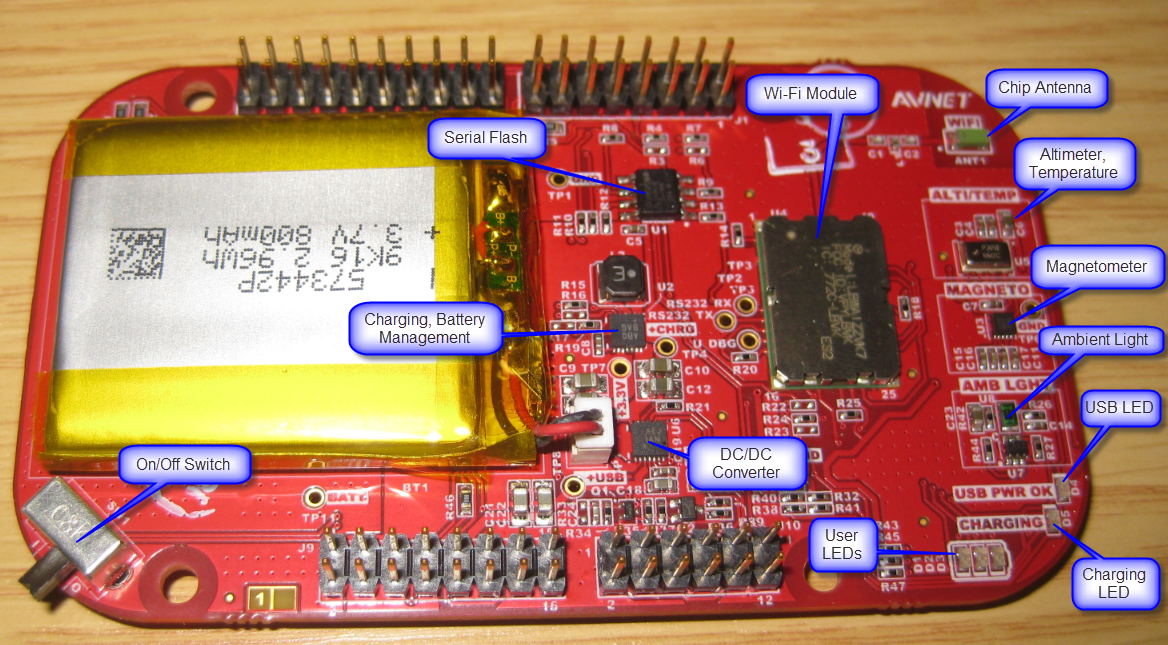
Parts on Wi-Go Board
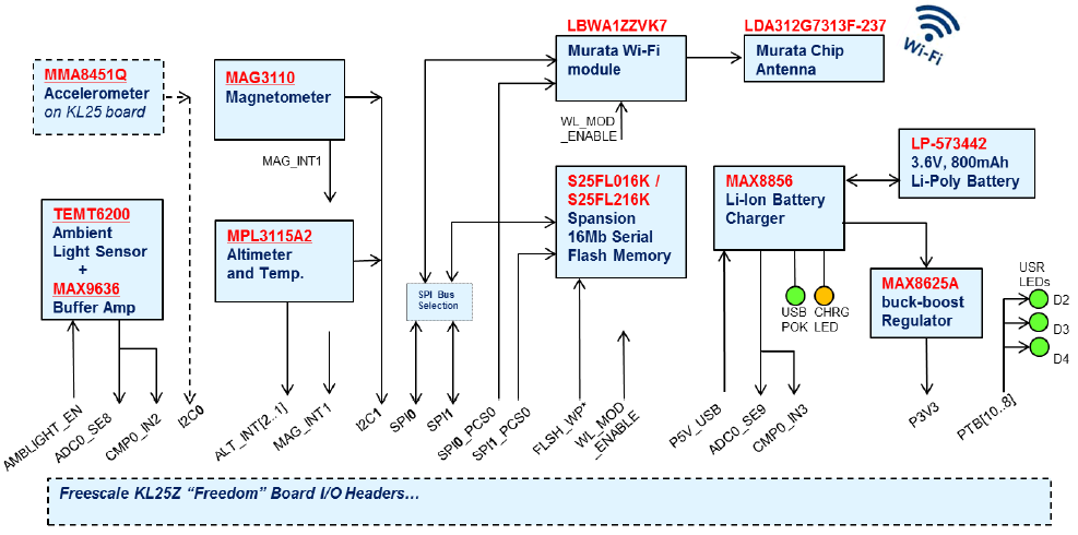
Wi-Go Board Blockdiagram (Source: Avnet)
With the Li-Ion battery pack, Wi-Fi capabilities and the on-board serial flash, this makes this board as great ‘sensor and data acquisition’ board. The battery is charged by the OpenSDA USB connector of the KL25Z Board (the KL25Z USB connector of the FRDM-KL25Z board does not charge the battery).
Headers
The Wi-Go board comes with male dual-row headers populated, matching the Freedom board header layout. The FRDM-KL25Z comes *without* headers, but most of the users I’m aware of have the FRDM-KL25Z populated with female headers ‘upside’ to have it compatible with normal Arduino shields. In order to fit the headers of the Wi-Go module, Avnet ships a modified version of the Freedom board with female headers on the downside:

Headers soldered downside on the FRDM-KL25Z for the Wi-Go Board
💡 It would be a good idea if the Wi-Go board would come with the 4 headers in a bag, and not soldered on the board. That way the user can choose the best connection method. I prefer to use the ‘long’ headers as this allows to stack more boards:

Long Headers on an Arduino Shield Board
With the headers downside on the Freedom board: that way the both boards build a very compact unit:
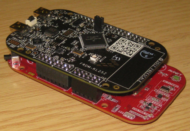
Stacked Freedom and Wi-Go Board
Now with the picture of both two boards it is clear why Avnet has selected that method: it is compact, and RGB LED and touch slider of the FRDM-KL25Z are still accessible. Another approach would have been to use ‘long’ headers on the Freedom board, and the Wi-Go populated with female headers: that way other Arduino shields could be stacked on top of the Feedom board.
Freedom Board Modifications
The headers populated downwards is not the only modifcation:
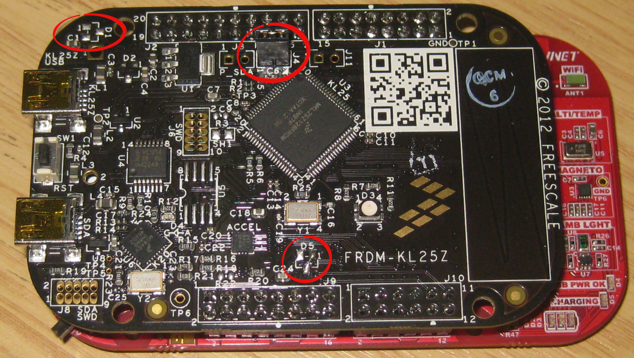
Freedom Board Modifications
- Headers downside (discussed this)
- Installed jumper J4 with trace cut on the backside to allow power measurement (according to Avnet, this jumper is only installed for the boards used in the initial workshops. The next build of the boards do not include that modification).
- Diode D1 removed. This allows the board turned on/off from the switch on the Wi-Go module.
- Diode D5 removed, with pin1 bridged to pin3 on D5 footprint (click on image to see detail). According to Avnet the voltage drop over D5 meant that only 4.2V is available at the input of the battery charger device, which is at the lower limit of the input range for this device.
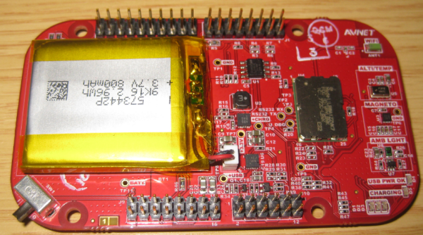
Not to miss this detail: The backside of the Wi-Go board comes nicely with signal labels printed on it, making probing much easier:
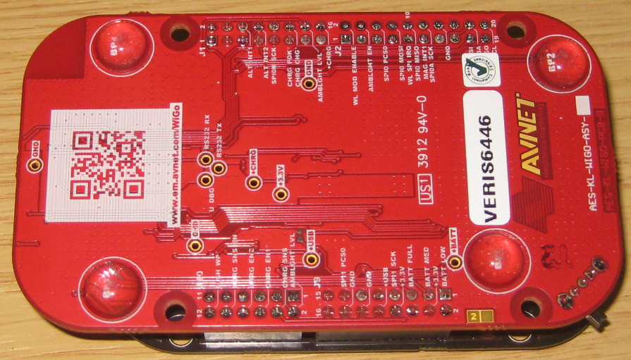
Wi-Go Board Backside
Software
Software and resources are available online (should be done these days on the web). I received a OpenSDA S19 file to program a test/demo software (with the MSD Bootloader MSD-FRDM-KL25Z_Pemicro_*.SDA programmed on the K20, see this article).
💡 My demo application had the .SDA extension, which let me think that this was an OpenSDA Application. Programming that file as OpenSDA application will not work. The demo application is a normal S19/SREC file (open it with a text editor), and can be loaded with the FRDM-KL25Z MSD Bootloader. So I renamed the Wi-Go_Webserver_Demo_*.SDA file I have received to Wi-Go_Webserver_Demo_*.SREC to avoid any confusion.
After the Wi-Go_Webserver_Demo has been flashed, the board reports sensor values through the OpenSDA USB CDC connection:
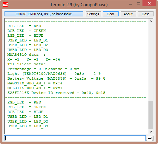
Diagnostic mode output
💡 The documentation suggests to use Tera Term. However, I had strange communication issues with Tera Term, maybe because I’m using Windows 8 (???). So I used Termite and things are working without issues.
💡 That repetitive test is a nice feature: I can immediately see that the board is doing something (and I see useful values over OpenSDA USB CDC). According to my Avnet contact this has been used as well for CE certification tests.
With pressing the Reset button on the FRDM-KL25Z, a menu shows up on the console:
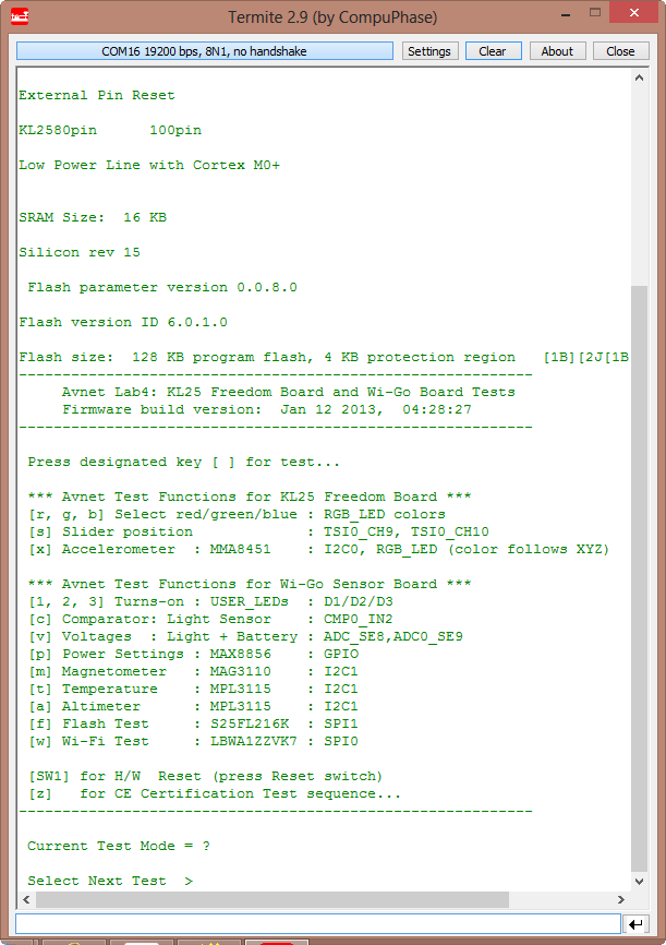
Menu after pressing reset
That way I can run each test. The most interesting menu select is ‘w’: to connect to the board to a Wi-Fi network.
Wi-Fi Connection
Now this is probably the most interesting part 🙂 : the Wi-Fi module. The Wi-Fi module can connect to a Wi-Fi access point (so it is not an access point itself, or a true ‘on-the-go’ device, according to the data sheet). But with more and more ‘ad-hoc’ Wi-Fi access points (e.g. with Android devices), this little board can be used ‘on the go’: with simply connecting to a wireless device like a mobile phone which acts as an access point: that makes a real cool usage of the module: say watching directly the sensor values from the mobile phone (Wi-Fi on the go) 😯 .
With software installed and in ‘w’ mode, it can connect to an access point with following parameters:
- SSID =”SPEEDWAY”
- WIRELESS SECURITY = WPA2 PSK
- KEY = “FREESCALE”
💡 The board is able to connect to an Android phone/tablet with ‘Wi-Fi hotspot’ enabled in Android. As I do not have an Android device, I used my home Wi-Fi router instead:
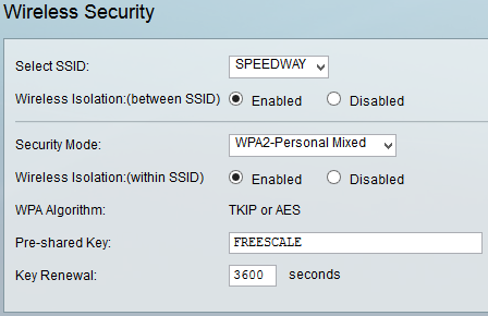
Cisco Wireless Router Security Settings
💡 I was *not* able to connect properly the Wi-Go board to my Cisco Wi-Fi Access Point with security enabled. Avnet has sent me a new S19/SREC file with security disabled, and this worked :-).
Pressing ‘w’ starts the Wi-Fi Web server on the Wi-Go board:
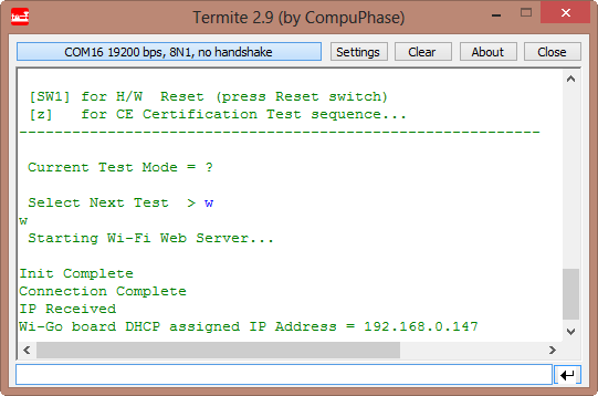
Started Web Server
The board reports the DHCP address I can use now in my web browser:
💡 Tip: copy-paste the address from the Terminal view to the web browser.
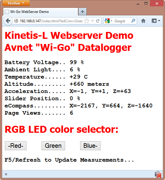
Web Server Demo
The web server reports the sensor values. Using the three buttons I can remotely select the color of the FRDM-KL25Z RGB LED. Really cool!
What’s next?
So far I have not written code for the board yet. Avnet has created the demo application with Keil MDK-ARM uVision4 which supports (among others) the growing number of Freescale ARM cores. But it should not be too difficult to port things to another tool chain. Anyway I’m using Processor Expert which makes porting even easier. I need to see how fast I can develop Processor Expert components for the Wi-Go board.
💡 A repository of Processor Expert components is shared on GitHub, see this post.
Summary
The Avnet Wi-Go is a great extension to the Freedom board, at a very reasonable price. There are a lot of cool features on the board, and Avnet’s software gives a quick start to the functionality of the board. Only that ‘header debate’ about which way the headers shall be populated (upside or downside) on the FRDM-KL25Z is causing some headaches. But for the low price of the FRDM-KL25Z it does not hurt to have two boards.
PS: Silica/Avnet have several live, face-to-face Kinetis-L Speedway training workshops featuring the Freedom board plus Wi-Go module where the focus is on achieving low-power portable operation using Freescale’s ultra low-power ARM Cortex-M0+ microcontroller devices. Some are still open for registration in UK, France, and North America with others following in Asia/Japan.
Happy Wi-Go’ing 🙂

Awesome!!! I want it now
LikeLike
I am drooling….
Is anything like it available on the west side of the world yet?
LikeLike
Awesome!
Wi-Go board + Freedom board + SD Card Module + Android Smartphone = Very fun projects!!
A lot of ideas come to mind 🙂
I am designing a Shield myself for a project in college and really is a challenge to optimize the use of resources, good job to the guys at Avnet and I’m looking forward to seeing your next projects based on this board.
LikeLike
for the ones in the USA/Canada/Mexico: there is a Wi-Go design contest ongoing:
https://www.em.avnet.com/en-us/design/trainingandevents/Pages/Avnet-Wi-Go-Design-Challenge.aspx
LikeLike
If someone combines this with Erich’s cute little robot so it can be controlled with Android, please let the rest of us know. It could be a great and fun project.
LikeLike
Hi Erich,
thank you for the great post!
Did you manage to get the Wi-Fi running? If yes can you share the code? Is the source code of the Avnet demo application available? I tried to find it but no luck.
Thanks in advance.
Best regards,
Panayot
LikeLike
Hi Panayot,
yes, I had the WiFi up and running.
As for the files: have you tried the download section on http://www.em.avnet.com/en-us/design/drc/Pages/Avnet-Wi-Go-Module.aspx
?
LikeLike
Hi Erich,
thanks for the reply. Yes I did check the Avnet website, but all I found was binary files and no source code. My final goal is to have an API between the CC3000 and the Kinetis MCU, so I am looking to start from a solid ground like a working project that has this or something close to this. Do you have any advise what is the best way to approach that problem?
Thanks.
Best regards,
Panayot
LikeLike
Hi Panayot,
I think I have received some source files from my Avnet FAE. I suggest you contact your local Avnet office if they could help you out?
LikeLike
Hi Erich,
OK I will try that.
LikeLike