
The Freedom KL25Z board has a great price of less than $15. Adding a typical LCD usually will add a multiple of that price to the budget. But hey, there is a way to add a LCD to that board at almost no costs! With the idea that I have an old outdated Nokia phone, and the cost of a small capacitor plus some wires are considered as ‘zero’ ;-).

Say Hello from the Freedom Board
All what I need is:
- An old Nokia phone with one of these monocolor LCD displays
- Disassemble the phone to grab the display
- Adding a small capacitor and wires to my FRDM-KL25Z board
- Using a Processor Expert component as display driver
- Having fun 🙂
Nokia ‘Classic’ Phones
A key reason for low price is high production volume. Similar to boards, this applies to other electronic goods as well, and this includes mobile phones. They are definitely produced in high volumes. Today is the area of smart phones, but not a long time ago Nokia was dominating the market with phones like the 3310:

Nokia 3310 Mobile Phone
The Nokia 3310 and similar models are still available today in second-hand markets for a handful Euros. Or even available free of charge if you collect them from recycling stations. what is of interest for me are the displays: the phone features a 84×48 graphical LCD display.
Another Way of Recycling
I had one as well years ago, and was very happy with it. It still works. Since then, it was in a box with other ‘old’ electronics intended to use maybe later on. And I guess many of you have the same thing: such an old phone stored somewhere. So I decided give my old phone a new life (well, only for the display). And I have asked around in my family, and guess what: they were happy to give me their old phones. Asking students: and I had even more old phone displays to use :-).
I have found that I’m able to use the displays from following phone types:
- Nokia 3210
- Nokia 3310
- Nokia 3330
- Nokia 5510
Disassembling the phone is rather easy. More problematic is to find out what kind of display/controller is used. Thanks to the SerDispLib project a lot of reverse engineering information is already available.
Type 1 or Type 2?
There are two different types of displays known:
 Type 1 displays
   +-----------------------+
   |    1 2 3 4 5 6 7 8    |
   +-----------------------+
   |                       |
   |       Rear View       |
   |(Connector is visible) |
   |       LPH7779         |
   +-----------------------+
Type 1 display has following pinout:
- 1: Vdd (+5V or 3.3V, up to 7.4 mA)
- 2: SCKL (SPI Clock)
- 3: MOSI (SPI Master Out Slave In)
- 4: D/C (Data or Command)
- 5: SCE (SPI Chip Enable (Chip Select, active low))
- 6: GND (Ground)
- 7: VOUT (Display voltage out, connect with 1-4.7uF to ground, not connected to the microcontroller)
- 8: RST (Reset, active low)
 Type 2 displays
   +-----------------------+
   |   1 2 3 4 5 6 7 8 9   |
   +-----------------------+
   |                       |
   |       Rear View       |
   |(Connector is visible) |
   |       LPH7366         |
   |                       |
   +-----------------------+
Type 2 display has following pinout:
- 1: Vdd (+5V or 3.3V, up to 7.4 mA)
- 2: SCKL (SPI Clock)
- 3: MOSI (SPI Master Out Slave In)
- 4: D/C (Data or Command)
- 5: SCE (SPI Chip Enable (Chip Select, active low))
- 6: External clock. Connect to Vdd.
- 7: GND (Ground)
- 8: VOUT (Display voltage out, connect with 1-4.7uF to ground, not connected to the microcontroller)
- 9: RST (Reset, active low)
Display Connector
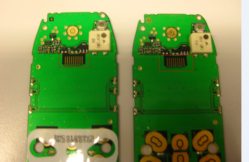
Basically the difference is the number of pins. I have found that some Nokia 3310 are especially useful as they have metal pins on the backside which makes it easy to solder wires on it, plus the needed capacitor:

Nokia 3310 Display Rear Side with Pinout
Other Nokia phones like the 5110 and 6150 are more problematic. The following picture shows the backside of the board:

Backside of Nokia 5110 and 6150
The issue is that not normal metal connectors are used. It uses kind of conductive ‘gum’ connector:

Nokia 6150 LCD connector
💡 Note the writing “LPH7366” on the backside of the display which tells me the display controller used :-).
So instead of using metal contacts, it is using such conductive material to connect to the board. For this, the LCD display is pressed on the front side contacts of the board:
Contacts on the front side of the board
The LCD itself has a metal frame which is clipped on the board. I decided to cut the board to have a connector plus the 6 green backlight LED on it:

Board Cut
To connect to the my microcontroller board, I had to solder connection wires, and clipped the board to the PCB:

Wired 5110 Display with LCD clipped on
Both the Nokia 5110 and 6150 have backlight LED’s on the board which I can use too :-). The picture below shows the board wired to a breadboard and the green backlight LED’s of the display turned on:

Breadboard Wiring with Backlight on
‘Gum’ Connector
But other (earlier?) Nokia 3310 are different again: their board has a lot of component on it:
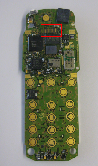
Nokia Phone Board with Connector
Here as well the ‘gum’ connector type is used:

Nokia 3310 Display with ‘Gum’ Connector
With these phones, the phone plastic cover is pressing the LCD on the base board. So for this kind of display another approach had to be used: a PCB with the connectors replicated and the capacitor on it:
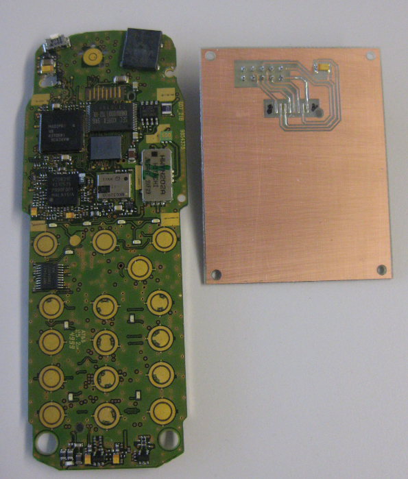
Connector PCB (Front Side)
The back side of the board has a 2×5 connector on it for easier wiring:

Connector PCB Back Side
Then the display needs to be pressed on the PCB to make contact:
Pressing Display on Connector PCB
A second revision of the connector board includes a plexiglass cover to press the display on the connector:
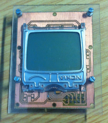
LCD with Plexiglass Cover
Additionally, the second revision of the boards integrates LCD’s with backlight LED’s:
Plexiglass cover with backlight LED display
Test Wiring to the Freedom Board
I used a bread board to connect the Display to the Freedom board. To verify the signals, a logic analyzer is used.

Connection to the Freedom Board
PDC8544 Processor Expert Component
According to the information in the internet, the display features a Philips PDC8544 controller. So the next thing was to develop a Processor Expert driver for it:

PDC8544 Processor Expert Component
The driver implements the low-level protocol and basic routines, including writing text to the display. Graphical routines like drawing lines/etc are subject of another component. But it is easy to write some text to the display with the low-level component.
As there are different variants of the display, the type of the display plus supply voltage is configured in the component properties:
PDC8544 Properties
Initialization Sequence and Communication Protocol
The display uses 5 communication lines (beside of GND and Vcc):
- D_C: Data or Command. Low for Command, High for Data
- CLK: SPI clock signal
- MOSI: SPI Master Out-Slave In
- RES: Display Reset line
- SCE: SPI chip select
The display has no MISO line, as it is not possible to read from the display.
The component Init() method initializes the display automatically:
- Setting RES and SCE to HIGH
- Waiting for 10 ms
- Setting RES to LOW
- Waiting 100 ms
- Setting RES to HIGH again
The sequence is best shown with a logic analyzer:

LCD Initialization Start Sequence
Next, a sequence of command bytes is sent to the display:

LCD Initialization Sequence
With 3V power supply, the sequence is 0x21 0xC8 0x13 0x 20 0x09, while for 5V display supply voltage it is 0x21 0xC2 0x13 0x 20 0x09.
The screenshot below shows the SPI details of the first command:
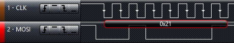
Sending 0x21 command
This means:
- 8bit per transfer
- MSB (Most Significant Byte) first
- Clock Idle Polarity high (CPOL=1)
- Data is valid on Clock Leading Edge (CPHA=0)
Using it with the Freedom Board
I used following connections on the FRDM-KL25Z Arduino header:
- D3: RES
- D8: SCE
- D9: D_C
- D12: MOSI
- D13: CLK
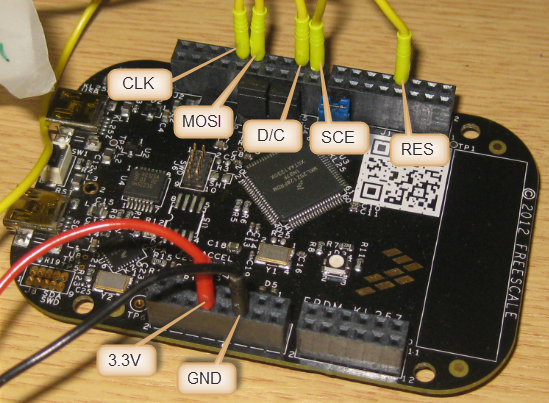
FRDM-KL25Z Board Connections
This means following connections for the KL25Z microcontroller on the FRDM-KL25Z board:
=================================================================
 SIGNAL LIST
-----------------------------------------------------------------
SIGNAL-NAME [DIR]        => PIN-NAME [PIN-NUMBER]
-----------------------------------------------------------------
CLK_D13 [Output]         => ADC0_SE5b/PTD1/SPI0_SCK/TPM0_CH1 [74]
D_C_D9 [Output]          => ADC0_SE6b/PTD5/SPI1_SCK/UART2_TX/TPM0_CH5 [78]
MOSI_D12 [Output]        => PTD3/SPI0_MISO/UART2_TX/TPM0_CH3/SPI0_MOSI [76]
RES_D3 [Output]          => PTA12/TPM1_CH0 [32]
SCE_D8 [Output]          => PTA13/TPM1_CH1 [33]
=================================================================
A Simple Demo Program
Here is how to create a simple demo program to test the display:
After having created a Processor Expert project in CodeWarrior for MCU10.3 (File > New > Bareboard Project), I add the PDC8544 component to my project. It will ask me to add a new Wait component. The PDC8544 will show an error as I need to further configure it:

Added PDC8544
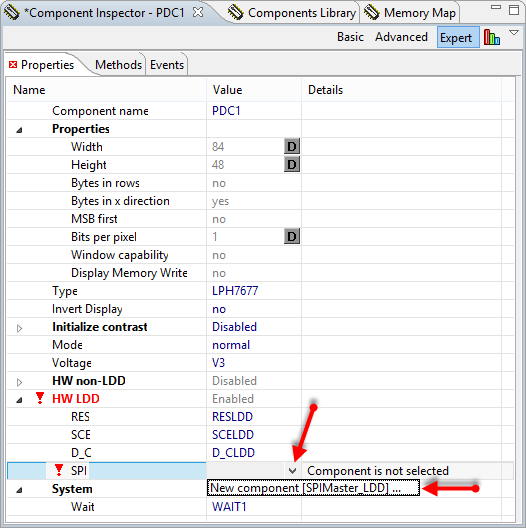
I need to add a new SPI component in the PDC1 properties:
Add new SPIMaster_LDD Component
SPI Bus, RES and D/C Signals
This will create a new SPIMaster_LDD component:
Note: Processor Expert in MCU10.3 creates a new folder ‘Referenced_Components’
The SPI component gets configured according to my pin mapping:
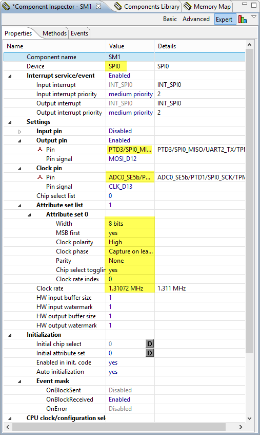
SPI Configuration
If communication does not work well, try a slower clock rate. For me it worked well above 1 MHz.
Next to configure the RES, SCE and D_C pins:

RES Pin Configuration

SCE Pin Configuration
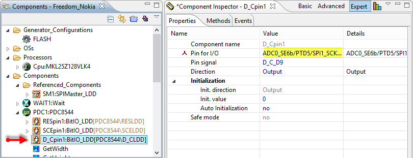
D_C Pin Configuration
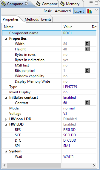
Display Settings
Finally, the display driver properties:
The Type has to correspond to the display type used. The following types are supported:
- LPH7366: Nokia 5110, 5120, 5130, 5160, 6110, 6150
- LPH7677: Nokia 3210, 5510
- LPH7779: Nokia 3310, 3315, 3330, 3350, 3410
The Contrast is a bit tricky: depending on the display type, that value needs to be set differently. LPH7677 and LPH7779 typically need a value of 68, where LPH7366 needs a value around 50. In doubt, you need to experiment with that value. Additionally you can change the contract using the SetContrast() method at runtime. Last but not least it is needed to specify the correct supply voltage of the display, as the initialization is different for 3.3V and 5V displays:

PDC8544 Display Properties
Writing Text
Now time to generate Processor Expert code and to add a few lines of code to write some text. WriteLineStr() writes a string to a line starting with number 1. To keep things simple I add my code into the main() routine in ProcessorExpert.c:
int main(void)
/*lint -restore Enable MISRA rule (6.3) checking. */
{
  /* Write your local variable definition here */

  /*** Processor Expert internal initialization. DON'T REMOVE THIS CODE!!! ***/
  PE_low_level_init();
  /*** End of Processor Expert internal initialization.                    ***/

  /* Write some text */
  PDC1_WriteLineStr(1, "Hello World");
  PDC1_WriteLineStr(2, "from the");
  PDC1_WriteLineStr(3, "KL25Z Freedom");
  PDC1_WriteLineStr(4, "Board!");
  /*** Don't write any code pass this line, or it will be deleted during code generation. ***/
  /*** RTOS startup code. Macro PEX_RTOS_START is defined by the RTOS component. DON'T MODIFY THIS CODE!!! ***/
  #ifdef PEX_RTOS_START
    PEX_RTOS_START();                  /* Startup of the selected RTOS. Macro is defined by the RTOS component. */
  #endif
  /*** End of RTOS startup code.  ***/
  /*** Processor Expert end of main routine. DON'T MODIFY THIS CODE!!! ***/
  for(;;){}
  /*** Processor Expert end of main routine. DON'T WRITE CODE BELOW!!! ***/
} /*** End of main routine. DO NOT MODIFY THIS TEXT!!! ***/
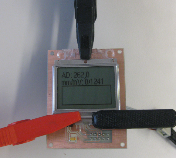
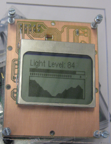
Compile, download and the result should be like this:
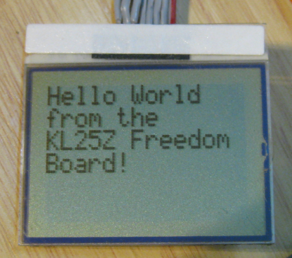
Hello World
Summary
I’m able to get a free-of-charge used Nokia phones, or very cheap replacement parts from the internet. With this and the Processor Expert component created, it is very easy to integrate a small graphical LCD display to my FRDM-KL25Z board (or any other board). Which is a great thing and enhancements of my Freedom board for many projects. I hope you enjoy it as I do.
Software
A demo project is available on this page. The needed Processor Expert components are available from www.steinerberg.com/EmbeddedComponents: Wait and PDC8544.
More? Yes!
Well, it does not stop here. There are other Processor Expert components to draw lines, boxes, circles, images and fonts, as already shown in some of the pictures above. But this is a subject for a follow-up blog :-).
Further Information
- Google for “Nokia spare parts display” and you will find many suppliers of Nokia used displays
- You can buy complete Nokia display kits: e.g. from Play-Zone
- Serdisplib Project on http://serdisplib.sourceforge.net/ser/pcd8544.html
- PDC8544 48×84 pixels matrix LCD controller/driver, Philips Semiconductor, 12-Apr-1999: http://www.sparkfun.com/datasheets/LCD/Monochrome/Nokia5110.pdf
Happy Nokiaing 🙂

Thank you very much for this post!!
LikeLike
Hi Erich, thank you for another wonderful project for the FRDM board!
I’d done quite a few projects (using AVR MCUs) with the NOKIA 3310 LCDs (LCD + keyboard assembly)…
I could buy them dirt cheap for US$ 1.50 (in India where I live) from mobile spare parts shops. Sadly, they have now disappeared :-(,
The Nokia 5110 LCDs are now available, but no longer at mobile repair shops….and they need to be bought already mounted on breakout boards … and this works much more expensive than the old favourite, the 3310 LCD.
LikeLike
I have found it more efficient to buy old phones for $1-2 instead of buying the displays only. Because I see that some are selling the displays for around $10, while the whole phone is much cheaper. Contacting the local recycle center might be a good source of plenty of old phones too.
LikeLike
Really impressive and insightful interface to the display. Thank you
LikeLike
Pingback: Page not found | MCU on Eclipse
I just had a look in a drawer and found 3 x Nokia 7110s – screwdrivers are coming out NOW! (I have 3 Freedom boards, in addition to the one I’ve modified to act as a programmer.)
LikeLike
Yes, the 7110s are very common, and are great for this kind of projects. Have fun 🙂
LikeLike
I see that the 7110 has a different resolution display – but I’m sure this could be adapted to suit. I’ve found the pinout, should anyone else want to try this: http://serdisplib.sourceforge.net/ser/sed1565.html
You also get a thermistor (could be used with ADC?) and a momentary switch on the board to play with – plus the backlight LED.
LikeLike
It is not only a different resolution, it is a different display controller too. So that would require some work.
LikeLike
Is your Processor Expert component configured for Kinetis only, or should it be usable with HCS08? (I see you have a Hardware Non-LDD thing in there, was wondering if this was for non-Kinetis parts.)
LikeLike
It works with any processor. I use that component for S08, ColdFire and Kinetis. Yes, that non-LDD is for non-Kinetis.
LikeLike
I cannot find the link to the codes for this project on this page
LikeLike
Yes, somehow the link is missing. The example projects page is here:
http://steinerberg.com/EmbeddedComponents/Examples/Examples.htm
PS: the latest development is available in the GIT repository: https://github.com/ErichStyger/mcuoneclipse/tree/master/Examples
LikeLike
Hi Erich,
It is ok to use Nokia 1112
LikeLike
Hi Alex,
I quickly checked, but it looks like the 1112 is using a different connector. But the problem is that it is using a different controller (Epson, and not the Philips one I support). See http://www.electricstuff.co.uk/noklcd.html
So I doubt it will work. Unless somebody contributes a driver for the Epson display controller?
LikeLike
Thank you.
LikeLike
Hi Erich, this could be compatible with nokia lcd sparkfun 6100?
LikeLike
Hi Braulio,
if you refer to https://www.sparkfun.com/products/569, then no, this one has a different resolution and size.
LikeLike
I have a proble with 9 bit data that request for this lcd, this example use 9 bit data?
LikeLike
Hi Braulio,
why do you think it is 9 bits? The display is using 8bit SPI data.
LikeLike
Hello! I am using this component in CodeWarrior 10.4 with a FRMD K20D50M with MQX Lite, I follow all the steps from post, and when the app call the method WriteCmd() don’t receive the DataReceivedFlag. Please do you know what it maybe happen?
LikeLike
It looks like this is an issue with interrupts and MQX-Lite. Can you try if it works for you without the RTOS?
The DataReceivedFlag gets set by the interrupt service routine. So if it is not set, it sounds like your interrupts are not properly enabled?
LikeLike
Yes that is! I put the initialization method of the LCD in the begin of the task of MQX Lite and the command sent successfully, but now the characters don’t show in the screen after the WriteLineStr, I will touch the contrast. Thanks! I hope the LCD screen works fine
LikeLike
I tried everything and the LCD don’t shine the pixels. The only don’t try is put the capacitor, but maybe I will search the arduino board to test the nokia 5110. Do you have something to recommend to know if the hardward works fine or is a software problem?
LikeLike
Hi Carlos,
you need to add this capacitor, otherwise I think it will not work. I have never tried it without this capacitor.
And have you set the type to ‘LPH7366’? And it could be that different displays are used in your Nokia 5110, so check the display type/(writing on it)? Contrast should be 50 for the LPH7366 (at least this worked for me).
If you google for ‘arduino nokia 5110 display’ then you get plenty of hits of companies which should be able to sell you such a display.
LikeLike
Thanks a bunch for the init sequence for the LCD. Was having quite a hard time figuring out how to init the LCD with my MSP430 Launchpad.
LikeLike
You are welcome! And yes, I had the same problem: getting the init sequence right was the most difficult part.
LikeLike
Erich.
Have you worked with the ST7565R or done a PE for the controller? there are some nice low cost monographic lcds with touch screen.
LikeLike
Hi William,
no, I have not worked with the ST756R so far.
LikeLike
Thanks Erich.
I thought there was an SPI LCD graphic interface in the PE modules you did but now I can’t seem to find it. Since I have to get it working I’ll send you what I come up with.
LikeLike
Super work sir….i having nokia 2102 display old model, it having 12 pins. how can i find pin configuration. Display backside many numbers are written which one is display modal number.
Thanks & Regards
Ikram Khan.S.I
LikeLike
Hello,
I’m sorry, but I’m not familiar with such a Nokia 2102, and when I quickly searched the internet, I have not found any useful information about it 😦
Erich
LikeLike
Could you please provide the custom board files?
LikeLike
I believe I don’t have the board files any more, as I do not use that program any more. If it helps, I could make some picture of the boards (they are only single sided).
LikeLike
Does anyone know what the voltage of Vout should be on 5110?
LikeLike
It should be around 6-9V.
LikeLike
We buy these displays in Kenya at local phone repair shops at Kshs 150, which translates to $1.73. I have used them with a zilog 8-bit microcontroller: https://github.com/Muriukidavid/z8_64k/blob/master/board.jpg, but thats in my little museum now. The good thing is that I can reuse with my custom kl05z boards now. Thanks for the contribution to the library of Processor Expert components, I enjoy using them. You seem to have made all the components I would think of making. I am making a new circuit tonight with this display for my undergrad students projects and I had to refer. Always a pleasure.
LikeLike
That board looks cool! Anyway, glad to hear that in some aspects I’m ahead of you, somehow 😉 And good to hear the the components are useful for you.
LikeLike
Hi Erich,
This post is very interesting and it works for me. How do I use the Gdisplay componen? When I try to write something, it says that the line is out of range. Do You have any ideas?
LikeLike
Hi Alex,
not sure about this error message: can you provide some more details? On GitHub (https://github.com/ErichStyger/mcuoneclipse/tree/master/Examples) I have examples.
LikeLike
Here is the project: https://drive.google.com
LikeLike
Hi Alex,
I had to enable GetWidth(), GetHeight(), GetLongerSide() and GetShorterSide() in Gdisp1. Then generated code, and I was able to compile. Maybe this is your problem?
LikeLike
It works! Thank you!
LikeLike
You are welcome! I know it is all about these details…. The driver has these functions disabled by default, maybe I need to change that.
LikeLike
hi Erich,
is there a reason why your PDC8544 PE component should not work with freescale ke02z board? I’ve tried with kz25z and it works perfectly, while I can’t get it on with ke02.
LikeLike
I don’t see a reason why it should not work with the ke02z. Are your signals 3.3V?
LikeLike
actually I thought ke02z logic level is 3.3v, although the board is supposed to be 5V. I will try to see if the 5V initialization solves the issue. The nokia 5110 lcd I’m using can handle 5V signals, I’ve used it with arduino and it seemed ok.
LikeLike
I have used the displays only with 3.3V logic, that’s why I asked. Can you check your wiring/connections, possibly with a logic analyzer? Maybe there is such a problem like wrong pins used?
LikeLike
Pingback: Snake Game on the FRDM-KL25Z with Nokia 5110 Display | MCU on Eclipse
what is the connection of the led in cell phone board 3310?
LikeLike
That depends on the model and board. You need to find the LED on the board and follow the traces. Then I added wires to the anode and cathode side.
LikeLike
Hi,
I am currently running this on a 32 bit version of the frdm kl25z board, it runs fine but there seems to be an error in timing somewhere along the line but I can’t figure out where this is. I have checked every output and stepped through, they all seem fine but yet the 3310 LCD screen is not displaying anything at all (I have plugged it into an arduino and tested the screen on there and it works fine).
Does anyone have any ideas?
Thanks
Tom
LikeLike
Hi Tom,
can you verify your signals to the LCD with a logic analyzer? It could be that you might have used wrong pins?
Erich
LikeLike
Hi Erich,
Thank you for the very speedy response!
I did verify most of the signals, however PD1 for the Clock is going to the built in LED. What would you advise for this?
Thanks
Tom
LikeLike
With that LED on your signal, you are very likely changing the signal characteristics, so this would be a reason why it does not work for you. I have used that such a ‘led signal’ pin for things like chip selects (no fast signal). Using that pin for a clock is very problematic.
Either use a different pin, or remove the resistor or LED for that signal path.
LikeLike
Hi Erich,
Apologies, tried changing all of the pins to no avail, I should get access to a signal analyser again in the next few weeks.
Thanks again for the help
Tom
LikeLike
Hi! I have seen that you dont have the wiring layout as a file, but do you know the spacing and width of the 8 pin gum connector?
Thank you!
LikeLike
Hi Steffen,
I would need to grab one of the displays and boards and measure it (I should be able to do this in a few days). I then could take a picture with measurement and post it here.
Erich
LikeLike
Further considerations: I think the spacing is about 1 mm apart. If you have a display with gum connector: check the gum connector on it, the conducting and non-conducting gum parts have a slightly different color. So if you have a display, you could measure it on the connector too.
Erich
LikeLiked by 1 person
Hi Erich!
Thank you! I have checked the gum connector and made it freestyle.
I made a pcb and it works! I am happy!
LikeLike
Excellent!
LikeLike
But i have to say i see why your second revision has a plexiglass plate on top. The connection with the gum is not very stable. 😦
For my use as a bike computer it is not usable. I think i have to order a version on a pcb or i have to look for a 5110 with the port connector.
LikeLike
In the Nokia phone, the upper frame/case is pressing the display and keep it in position. This is why I used a plexiglass to press the display down. It is still not very reliabel that way (I need to adjust it from time to time). A better way would be to glue it in position horizontally. Still you need to press it down to the contacts.
You are far better of with contacts you can solder. Or simply order a display which has that problem solved, e.g. the display I have used in this post: https://mcuoneclipse.com/2014/07/04/snake-game-on-the-frdm-kl25z-with-nokia-5110-display/. Link to where I have ordered it is in that post too, just in case.
LikeLike
And another thing. I found the correct name of this gum connector type. Its name is zebra connector. Hope that helps other people when angry about this evil connector type.
LikeLike
Hi! Those ‘gum’ connectors, from what I know, are called elastomeric connectors. I’ve tried to scavenge an LCD from an old guitar tuner and it had one of these connectors. At the time I didn’t know how I could use it, so I just put it back together.
LikeLike
Thanks, now I know the proper name for them 🙂
LikeLike
Hi guys and Erich Styger.
I´m beginner with FRDM K64F and i need to interface it with a GLCD like this:
http://ee-engineer.blogspot.com.ar/2010/10/graphic-lcd-240×128-graphic-lcd-module.html
Is there a post in this blog related to how to interface a 240 x 128 GLCD with the FRDM K64F?
LikeLike
Hi Juan,
I’m sorry, but I do not have a tutorial for this. But you could have a look at my code/components for the TWR-LCD instead.
LikeLike
Hello Erich,
I have installed your PE component pack to my KDS 3.0, and I noticed that now, at least for my FRDM-K64 board, the SPI component asks for some extra parameters (right below “Clock rate”): “Delay after transfer”, “CS to CLK delay”, and “CLK to CS delay”. What values should I use for my Nokia5110 display?
Thanks,
Antonio
LikeLike
Hi Antionio,
with this values you can delay the transfer. I usually set a low (if possible zero) delay.
LikeLike
Pingback: Prototype of Wireless Remote Controller with NXP Kinetis K20 | MCU on Eclipse
Pingback: INTRO Robot Remote – First Production PCB | MCU on Eclipse