
There was one part missing to complete the software support for my Arduino DataLogger Shield on top of my FRDM-KL25Z Freedom board: support for the Maxim DS1307 RTC (Real Time Clock).
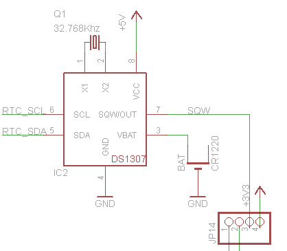
DS1307 on the Adafruit Data Logger Shield (Source: http://www.ladyada.net/make/logshield/design.html)
Things got delayed a bit, as I first needed to get the I2C infrastructure up and running (see this post). But finally, I have things working :-). I proudly present: RTC_Maxim!
Maxim I2C Real Time Clocks
The component now supports two different Maxim I2C Realtime Clocks: the DS3232 and the DS1307.
The DS1307 present on the Adafruit Data Logger Shield:
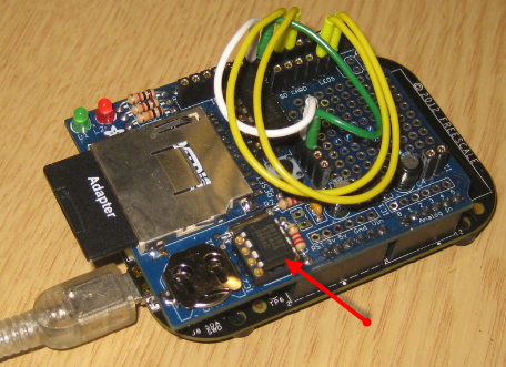
DS1307 on the Arduino Data Logger Shield, on top of the FRDM-KL25Z
The DS3232 is a device I have used in many of my designs:
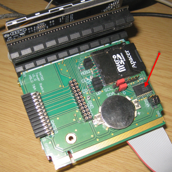
DS3232 on custom Tower Board
For ‘classic’ (non-LDD) Processor Expert, there has been a component (RTC_I2C_DS1307) for the DS1307 with my custom extensions for the DS3232. But as with many other things: these ‘classic’ components do not work for Kinetis, as with Kinetis there are LDD (Logical Device Driver) components, and they are not compatible. That’s why I ended up implementing my own RTC_Maxim component which works both for the LDD and non-LDD world (see as well this post).
RTC_Maxim Processor Expert Component
The component takes advantage of the GenericI2C component.
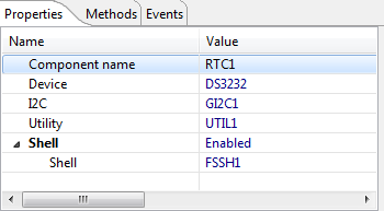
Properties of the RTC_Maxim Processor Expert component
As ‘Device’ either the DS3232 or the DS1307 can be selected. The component features an optional Shell interface (ParseCommand()) to the FSShell. Beside of this, it features the usual functions to get/set date and time:
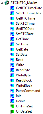
Methods of the RTC_Maxim Processor Expert component
The Read() and Write() methods are used to to access the device non-volatile memory and registers.
Limitations
The component now only supports date and time functions, plus access to the device non-volatile RAM. Support for the other features (temperature sensor, alarm functions, oscillator output, etc) would be a topic for further work. Maybe somebody volunteers to extend the current functionality?
Component Sources
The component (and sources) can be downloaded from this link: RTC_Maxim. The FSShell and FAT_FileSystem components have been updated as well with new interfaces.
Happy Maximing 🙂

Thanks, I have been looking to get RTC functionality working on my freedom boards and I have just ordered a DS1307 so this should be very useful 🙂
I do have one question though, why not use the internal RTC on the M0+ (RTC_LDD component)? Surely this should provide a lower-power option with all alarm functionality, etc. already there. I have been trying to get this working but I am running into clock source problems (cannot source from anything except ERCLK32K, which in turn needs to be sourced from external as the LPO under clocks it and PE won’t generate the code).
LikeLike
I used the Maxim RTC’s (especially the DS3232) in many other projects, where the microcontroller did not had an internal RTC, or where the microcontroller RTC was not accurate enough. And having some external battery buffered RAM was a plus too. AS for the KL25Z internal RTC, it needs to be sourced by an external 32 kHz crystal as far as I can tell, so it would require a board change to make it work (unless someone has another idea?).
LikeLike
Thanks for the reply Eric, that certainly makes sense re. the use of the RTC. Unfortunately, I am looking to use the internal alarms. I am still tempted to get this working as the DS1307 has a 32k square wave output and might be useful for other projects.
Just on another note, I have been trying to follow this guide but I am having trouble importing the GenericI2C into CodeWarrior – the component doesn’t show up and all I get on import is the GenericSWI2C and this causes the Maxim_RTC driver to fail to import. Do you have any ideas/comments on this?
LikeLike
Hello,
have you loaded both components from here:
– http://steinerberg.com/EmbeddedComponents/GenericI2C/home.htm
– http://steinerberg.com/EmbeddedComponents/GenericSWI2C/home.htm
?
LikeLike
Yep, I have installed both modules and I only see GenericSWI2C in the component list. This is on two diufferent machines running Codewarrior 10.3
LikeLike
Hello,
maybe I missed something. Could you check if you have this folder present?
C:\ProgramData\Processor Expert\CWMCU_PE5_00\Beans\GenericI2C
LikeLike
No, I don’t appear to have that folder on either machine and re-importing doesn’t pull it in – I only appear to get the GenericSWI2C when I import the DenericI2C package. I am using the GenericI2C_1.001_04.12.2012.PEupd download from your site.
LikeLike
Hello, indeed, the zip file has the wrong component in it :-(. I have now uploaded and updated the web page (http://steinerberg.com/EmbeddedComponents/GenericI2C/home.htm) with the (hopefully correct) component inside (Rev. 1.002).
Thanks for reporting!
LikeLike
hi Erich, i am using your DS1307 maxima componect with I2C_LDD and my code is stuck in /* Wait until data is sent */ of GI2C1_ReadAddress function.
i check hardware, its working. i checked the pins by toggling them.
i have verified the clock setting as mention in https://mcuoneclipse.com/2012/12/05/kl25z-and-i2c-missing-repeated-start-condition/
can you please help me, i have wasted 6 hours figuring what might have gone wrong.
the internal RTC works fine. but the project requirement is to have a DS1307 RTC with an Eeprom….so have to get this problem solved.
LikeLike
Hello,
this means that dataTransmittedFlg never gets set? Are your interrupts enabled (and not disabled by chance)?
Does I2C1_OnMasterBlockSent() get called?
LikeLike
Hi Erich.
I have been working with RTC for almost a week now. I want to ask you for your hardware set up for DS1307. I know DS1307 use 5 Volt VCC and KL25Z use 3.3 Volt VCC. How do you interface the pull up resistor for SDA and SCL between DS1307 to KL25Z? Do you use 5 volt or 3.3 volt as the VCC? What is the pull up resistor value? (2.2k Ohm) What setting value for your SCL frequency, SDA Hold, SCL start hold, and SCL stop hold? I am having same problem with previous post: “wait until data sent”. I use a working example from Freescale “accelerometer_demo”. When I use for DS1307 with different pint, I did not get any dataTransmittedFlg complete. So I do not know is this a hardware problem wrong VCC value? (I use 3.3 Volt for my SDA and SCL pull up resistor) Wrong Set up problem? (Incorrect SCL frequency, SDA Hold, SCL start hold, and SCL stop hold) or other problems?
Thanks.
LikeLike
Hi Harry,
Maybe check out this project here (https://github.com/ErichStyger/mcuoneclipse/tree/master/Examples). I’m using the FRDM-KL25Z with that Arduino Data Logger shield shown in this article.
You might use that project as it only uses the RTC and some pins for LED/push button and relay outputs.
Be aware that there is a hardware bug with the I2C in the KL25Z (and many other Freescale ARM cores as far as I know). See https://mcuoneclipse.com/2012/12/05/kl25z-and-i2c-missing-repeated-start-condition/
My settings:
MKL25Z with 8 MHz external crystal, 48 MHz core clock
I2C clocked with 24 MHz, SCL 125 kHz
SDA hold 0.708 us
SCL start hold 3.917 us
SCL stop hold 4.042 us
The hardware schematics/etc you can find here:
I recommend that you check your I2C signals with a logic analyzer.
I hope this helps?
LikeLike