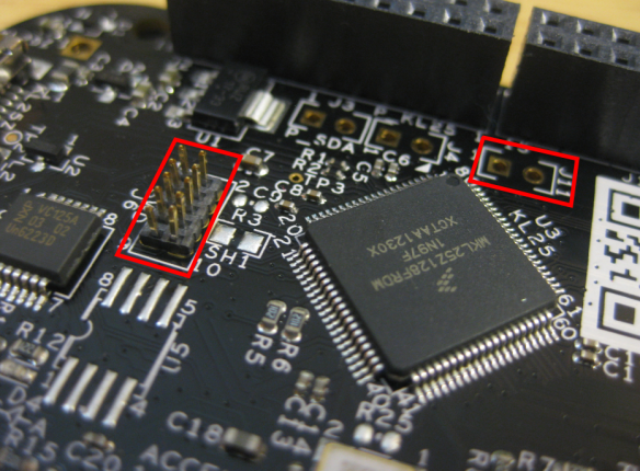
The OpenSDA on the FRDM-KL25Z board is a cool feature: I do not need any external debugging device to program and debug my board :-). But my KL25Z custom board will not have that OpenSDA on it: first because it would add additional costs, and I do not see a way how I could use it for my board. I better start using a SWD/JTAG debugger for my Freedom board to have everything in place.
What I need to add to the black Freedom board is the SWD header:
💡 With that header usually both JTAG and SWD debugging is possible. If it is SWD (lower pincount) or JTAG depends which microcontroller signals are routed to the header. But many times the terms JTAG and SWD are mixed even if technically not correct.
For the part numbers see this post.
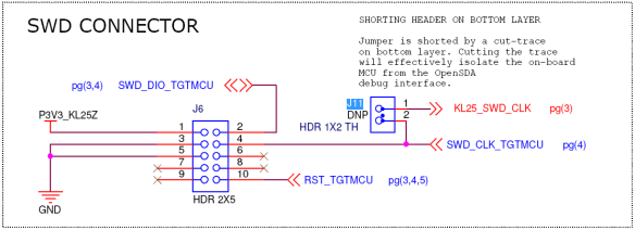
Looking at the schematics and the SWD connector, there is a J11 jumper (unpopulated) which can isolate the SWD (Single Wire Debug) clock signal between OpenSDA and the target.
The Freedom Board User Guide (chapter 5.2.1 Debug Interface) seems to indicate that it is possible to cut the J6 trace and then to debug another board with the connector. However, this is not possible, as it seems that the OpenSDA firmware is tight to the processor on the board. You will receive an error that this is not possible:
💡 Cutting that trace is *not* needed for me to debug the target over the SWD connector. Cutting that trace is *only* needed if I want to debug another board with OpenSDA (e.g. see “Using the Freedom Board as SWD Programmer“). For debugging the FRDM board with an external SWD cable the trace/jumper has to be installed!
The good thing is that I can use my existing P&E Universal Multilink. The debugging connection settings are very transparent between OpenSDA and USB Multilink: all what I need to do is to change the interface in the run/debug launch settings:
With this, ready to connect the Multilink with the Freedom board:
❗ Do *not* power the board with the OpenSDA USB port if debugging with a SWD/JTAG cable! Use the KL25Z USB connector as shown in the picture above! I have been told that otherwise either the diode D1 or D2 on the board might get burned, so be warned! I have not seen that problem for myself.
Debugging with the P&E Multilink just worked fine. OpenSDA already is pretty fast, but felt that using the Multilink was even a bit snappier. In any case, if OpenSDA would not be able to connect to my KL25Z on the Freedom board, I have now a second way to get access to it. And something like this has been always been useful for me in the past. I hope I have not to count on it, but always good to have it 😉
Happy SWDing 🙂


Hi Erich
I installed the headers and cable but am unsure of the instructions. I want to use the Freedom board as a pod. So I connected from my custom k20dx256z JTAG to J6, and connected the pc usb to the SDA. But I get no connection in CW although the drivers installed. I built a new connection with the OOSJTAG – USB port and left the interface as USB Mulitlink. But I get no connection. Do you have any advice please?
LikeLike
Hi Robert,
to my knowledge it is *not* possible to use the OpenSDA/Freedom board as a pod, as the firmware on the K20 is tight to the serial number on the KL25Z.
Erich
LikeLike
First a caveat: I have not tried this yet. However, based on discussions with Michael Norman of Freescale and also looking at the FRDM-KL25Z User’s Manual, this should be possible. Instructions are in 5.2.1 beginning on page 7. The key seems to be cutting a trace on the bottom side of the FRDM board that connects the SWD_CLK to the KL25Z MCU so the KL25Z won’t interfere with communication between the K20 and whatever offboard MCU you have connected via J6.
LikeLike
Yes, I have seen that, but not tried it neither. I have already cut that trace and I’m using a jumper to get the trace back. I will try it out if it works and report back.
LikeLike
Hi Roger, I tried this now, as you suggested, and it does not work for me. Error 17926 is shown. I have updated the post with that information. So as I feared: this does not work for me.
LikeLike
I even had my Freescale FAE tell me that I could use the KL25Z Freedom Board to program my kinetis µP for my projects and pointed me to the same 5.2.1 document. I’ve tried it today and also get the 17926 message. I’ve also tried copying the s19 .HEX file to the freedom board and that does not work either.
Don’t let the name “Freedom” fool you with their Freedom boards. PEMICRO does not want to lose sales on their $119 Multilink or $399 Multilink FX by having some $12.95 toy do the job.
BTW, since it is now March, do you know if there have been any recent solutions to the Freedom boards to allow the user to program external processors?
LikeLike
I have borrowed my FRDM board with the JTAG headers to a friend, so I cannot try it out. But I saw that P&E has published on their website (www.pemicro.com/opensda) a new firmware (Jan 7th). So it could be that this one supports programming another processor.
LikeLike
Hello Erich,
I have ordered a P&E Multilink for debug my custom board (KL25Z). My question if the wire that you have used in the photo (https://mcuoneclipse.files.wordpress.com/2012/11/freedom-and-multilink-side-by-side.png?w=584&h=414) is delivered with the Multilink or you have bought apart. In this later case, can you post the reference please?
Regards,
Juan
LikeLike
Hi Juan,
At that time it came only with the ‘wide’ Cortex. I have ordered the ‘small’ Cortex debug cable from Farnell (part number 1667659, see https://mcuoneclipse.com/2012/10/23/completing-the-frdm-kl25z-board/). However it is possible to use the delivered ‘broader’ cable too (just use/connect with part of the rows). Mayb P&E delivers now the small cable too.
LikeLike
Hello Erich,
I have a board with KL25Z,I develop it with IAR,but i “Download and Debug” with jlink,It runs well,
but re-plug jlink ,it runs abnormal..
LikeLike
Hi TinyHang,
not sure what this is, but it sounds like IAR is doing some additional initialization during download and debug?
LikeLike
Hi Erich,
Nice documentary. P&E shall have thanked you for all these useful tips.
I’d like add one tip: If you use Code Warrior to debug with MultiLink USB, you have to make one critical selection in Code Warrior IDE. If not, the debug will always tell you can’t connect to device, but it doesn’t tell you the problem.
Click on Debug Configuration->Edit, Select USB Multilink in “Interface”. Then in “Additional Options”, tick “Use SWD reduced pin protocol for communications”. Then click “OK” to apply changes.
It will be much nicer for P&E having this in your manual.
Cheers,
Michael
LikeLike
Hi Michael,
thanks 🙂
That ‘SWD vs. JTAG’ is not a P&E only thing: it applies to other ARM run control solutions like Segger too. You are right: without the proper selection, it is not possible to talk to the device. As a general rule: if using the small 10pin ribon cable, then ‘SWD’ needs to be selected, otherwise ‘JTAG’. As the default is JTAG, it happened to me several times to miss that setting change too. It would be nice if there could be an automatic detection of the setting, or that the run control unit would try the other setting in case of failure.
LikeLike
Hi everyone,
I’d really like to emphasize that you can’t program the FRDM-KL25Z or FRDM-KL46Z boards with a P&E programmer if you cut the trace! Cutting the trace will result in the following error:
“Error launching test01_FLASH_PnE U-MultiLink
ARM GDI Protocol Adapter : Can’t connect. The Debugger can not connect to the P&E device”
Me and a coworker spent half a day trying to figure out why CodeWarrior kept giving us this error. In fact, a lot of people are confused about this in the Freescale Community forums! Like most people, we cut the trace, got the error and then we thought that there was a problem with the drivers. So we manually updated and re-installed the Jungo drivers many times and we reset our computers after each re-install. Huge waste of time!
Finally, I saw this post by Erich and read that he didn’t cutoff the trace to get his P&E Multilink to work. Then I put a jumper to join the pins and the program was finally downloaded to the FRDM-KL46Z!
Please, if you see people posting about this problem then first ask them if they cut the trace before sending them to re-install their drivers! It will save them a lot of trouble.
Thanks and let’s spread the word!
LikeLike
Hi Carlos,
sorry to hear that you had problems with that jumper/trace :-(. That J11 jumper only needs to be disconnected if using OpenSDA to debug/program another board, see https://mcuoneclipse.com/2013/04/21/using-the-freedom-board-as-jtag-programmer/
LikeLike
Hi Erich,
It’s ok, we figured it out eventually 🙂 However, it would be nice if we could figure out a way to spread the word about the jumper and programming with a P&E Multilink. Like I said, the Freescale Community forums are filled up with people going crazy thinking they have a problem with drivers. (That can happen, but it’s easier to check first if they have cut the trace)
For now, I posted a comment on your post “Using the Freedom board as an SWD programmer” to let people now what to do if they have this problem. But it might just get lost within all the other comments. Maybe it’d be easier to see if it was mentioned within the post itself?
Frohes neues jahr!
LikeLike
Hi Carlos,
yes, good suggestion. I have made a note in the post itself. Thanks!
LikeLike
Thank you for your post. The FRDM-KL25Z handbook was quite fuzzy.
I can positively confirm that the FRDM-KL25Z works with Segger J-Link:
– J11 closed
– Connect J-Link via J6
– Power the FRDM-KL25Z via the KL25Z USB
LikeLike
Hi Herman,
I think it does not matter if you power the KL25Z with the USB or OpenSDA port, right?
LikeLike
Pingback: How to Recover the OpenSDA V2.x Bootloader | MCU on Eclipse
Pingback: Tutorial: Using Single Wire Output SWO with ARM Cortex-M and Eclipse | MCU on Eclipse
Is it possible to use p&e usb multilink with frdmkl25z?
LikeLike
Yes. I’m wondering about your question, as this post shows exactly that? See https://mcuoneclipse.files.wordpress.com/2012/11/freedom-and-multilink-side-by-side.png
LikeLike