The Kinetis ARM Cortex-M4(F) is a wonderful machine: a 32bit architecture, plenty of FLASH and RAM, an ideal play field. I love the Kinetis Tower boards, and even more the Freedom board which has an ARM Cortex-M0+ on it. I have a lot of projects on S08, S12 and ColdFire at the university, and they are all using a lot of Processor Expert components. Processor Expert is such a great productivity tool: having software in components allows easy software re-use. With Processor Expert abstracting from the hardware, I can easily port my applications to new boards and processors. Well, until Processor Expert changed for Kinetis :-(.
Time to deal with this. There are two blocking points: the concept of LDD, and availability of components.
Logical Device Driver
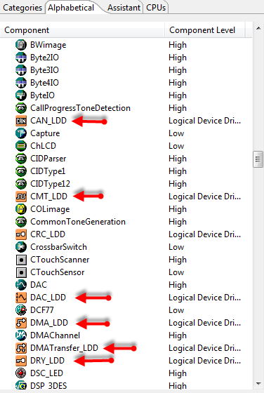
Processor Expert for Kinetis introduces the new concept of LDD or ‘Logical Device Drivers’. LDD components have a LDD suffix (sic!), and are using an orange color icon in the Components Library View:
LDD components are very different from the ‘classical’ Processor Expert components I used and have created: they are more oriented to work with an RTOS. For example let’s have a look at the GPIO_LDD component. That component deals with a general purpose I/O port:
This component corresponds to the BitsIO (non-LDD) component:
Example LDD: Init() and Deinit()
The two components offer pretty much the same thing, but the API is completely different. The LDD component has Init() and Denit() functions. Below is the code of the GPIO_LDD Init():
LDD_TDeviceData* GPIO2_Init(LDD_TUserData *UserDataPtr)
{
  /* Allocate LDD device structure */
  GPIO2_TDeviceData *DeviceDataPrv;

  /* {FreeRTOS RTOS Adapter} Driver memory allocation: RTOS function call is defined by FreeRTOS RTOS Adapter property */
  DeviceDataPrv = (GPIO2_TDeviceData *)pvPortMalloc(sizeof(GPIO2_TDeviceData));
  #if FreeRTOS_CHECK_MEMORY_ALLOCATION_ERRORS
  if (DeviceDataPrv == NULL) {
    return (NULL);
  }
  #endif
  /* Save RTOS Device structure */
  DeviceDataPrv->EventFlags = 0x00U;   /* Clears stored events */
  DeviceDataPrv->UserData = UserDataPtr; /* Store the RTOS device structure */
  /* Interrupt vector(s) allocation */
  /* {FreeRTOS RTOS Adapter} Set interrupt vector: IVT is static, ISR parameter is passed by the global variable */
  INT_PORTE__BAREBOARD_RTOS_ISRPARAM = DeviceDataPrv;
  /* GPIOE_PDDR: PDD&=~0x10000000 */
  GPIOE_PDDR &= (uint32_t)~0x10000000UL;
  /* Initialization of Port Control registers */
  /* PORTE_PCR28: ISF=0,LK=0,MUX=1 */
  PORTE_PCR28 = (uint32_t)((PORTE_PCR28 & (uint32_t)~0x01008600UL) | (uint32_t)0x0100UL);
  /* PORTE_PCR28: ISF=1,IRQC=0x0B */
  PORTE_PCR28 = (uint32_t)((PORTE_PCR28 & (uint32_t)~0x00040000UL) | (uint32_t)0x010B0000UL);
  /* NVICIP91: PRI91=0x80 */
  NVICIP91 = (uint8_t)0x80U;
  /* NVICISER2: SETENA|=0x08000000 */
  NVICISER2 |= (uint32_t)0x08000000UL;
  /* Registration of the device structure */
  PE_LDD_RegisterDeviceStructure(PE_LDD_COMPONENT_GPIO2_ID,DeviceDataPrv);
  return ((LDD_TDeviceData *)DeviceDataPrv);
}

void GPIO2_Deinit(LDD_TDeviceData *DeviceDataPtr)
{
  (void)DeviceDataPtr;                 /* Parameter is not used, suppress unused argument warning */
  /* PORTE_PCR28: IRQC=0 */
  PORTE_PCR28 &= (uint32_t)~0x000F0000UL;
  /* GPIOE_PDDR: PDD&=~0x10000000 */
  GPIOE_PDDR &= (uint32_t)~0x10000000UL;
  /* Interrupt vector(s) deallocation */
  /* {FreeRTOS RTOS Adapter} Restore interrupt vector: IVT is static, no code is generated */
  /* Unregistration of the device structure */
  PE_LDD_UnregisterDeviceStructure(PE_LDD_COMPONENT_GPIO2_ID);
  /* Deallocation of the device structure */
  /* {FreeRTOS RTOS Adapter} Driver memory deallocation: RTOS function call is defined by FreeRTOS RTOS Adapter property */
  vPortFree((GPIO2_TDeviceDataPtr)DeviceDataPtr);
}
I highlighted line 7 and 48 which is using the RTOS dynamic memory allocation through the RTOS adapter.
Compared to the ‘old fashioned way’ of Processor Expert components, using the LDD is not that simple and straight forward. As shown with the two above functions, I need to think about a Device Data structure and pass this along through the API. So things get more flexible, but as well much more complicated. So setting a big of an I/O port is not a simple Macro any more:
void GPIO1_SetFieldValue(LDD_TDeviceData *DeviceDataPtr, LDD_GPIO_TBitField Field, GPIO1_TFieldValue Value)
{
  (void)DeviceDataPtr;                 /* Parameter is not used, suppress unused argument warning */
  switch (Field) {                     /* no break */
    case LED_E4: {                     /* bit field #0 */
      GPIO_PDD_SetPortDataOutput(GPIO1_MODULE_BASE_ADDRESS,
        (
        GPIO_PDD_GetPortDataOutput(GPIO1_MODULE_BASE_ADDRESS)
        & ((GPIO1_TPortValue)(~((GPIO1_TPortValue)GPIO1_LED_E4_MASK)))
        )
        | (
        ((GPIO1_TPortValue)(Value << GPIO1_LED_E4_START_BIT))
        & ((GPIO1_TPortValue)GPIO1_LED_E4_MASK)
         )
       );
       break;
     }
     case LED_E1: {                     /* bit field #1 */
...
     }
    default:
      break;                           /* Invalid Field is not treated, result is undefined */
  } /* switch (Field) */
}
Instead, I need to pass several parameters. Yes, very flexible. But the footprint and run-time impact are not small. The ‘new’ way is much more suited for larger and dynamic systems, especially if you are using things like an MQX operating system. But as I am coming from the embedded world where ‘small and fast’ is key, this new LDD way was a shock. On the other side: the Kinetis is such a powerful architecture, maybe this does not matter? Time will tell.
Porting Applications
There is something else which really matters: all my code and and all my Processor Expert components did *not* work any more with this new concept :-(. Boomer. Away was the promise of ‘develop with Processor Expert, and you can easily migrate to other cores’. True, but not if I want to migrate to Kinetis :-(. I would say this was one of the biggest obstacles for me to move to the more powerful ARM cores. The ARM core already is very different, and this time even Processor Expert was not a big help with the transformation, unlike it was before to migrate between cores.
LED Example: Dual Interface
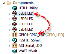
So it looks like I need to bite the bullet. Since then, I try to workaround the problem, and adding dual interfaces to my components. An example for this is the LED component which offers a ‘traditional’ (non-LDD) interface, but as well an interface to the LDD components:
Here one or multiple LED components is linked to a GPIO_LDD component. This is set up in the LED component with the enabled LDD settings:
I need to specify a field name (e.g. “LED_E1”, more about this below), which component to link to (e.g. “GPIO1”) and if the Init() functions of that LDD shall be called from the LED component initialization during PE_low_level_init() or not.
In the GPIO_LDD I set up my pins for that port, and the linkage between the LED component and the GPIO_LDD component with the Field Name (“LED_E1” in this example):
So how does this dual way works? Below is the example of the LED On() in the driver code:
void %'ModuleName'%.%On(void)
{
%if AnodeOnPortSide = 'yes'
  %if defined(GPIO_LDD) %- using LDD
  %@GPIO_LDD@'ModuleName'%.SetPortBits(NULL, %@GPIO_LDD@'ModuleName'%.%'GPIO_LDD_BitfieldName'%.MASK);
%else
  %@LEDPin@'ModuleName'%.SetVal();
%endif
%else
%if defined(GPIO_LDD) %- using LDD
  %@GPIO_LDD@'ModuleName'%.ClearPortBits(NULL, %@GPIO_LDD@'ModuleName'%.%'GPIO_LDD_BitfieldName'%.MASK);
%else
  %@LEDPin@'ModuleName'%.ClrVal();
%endif
%endif
}
For non-LDD components, it is simply using ClrVal() and SetVal() which actually are macros. For the LDD version it is using ClearPortBits() and SetPortBits() with NULL parameters as no RTOS or device parameter is requested.
The generated code looks this in the LDD world:
void LED1_On(void)
{
  GPIO1_ClearPortBits(NULL, GPIO1_LED_E1_MASK);
}
That dual interface is not ideal, bloats up the properties and the driver code, but at least that way I can use the components both for the non-LDD and LDD world.
What is available?
The other thing I run into is that a component is available, but not for Kinetis. I was porting one of my applications, and this application is using the TimeDate component which manages date and time information. “No problem”, I thought, as I had it listed in the Components Library:
But I get an error that this component is not supported in this version (of CodeWarrior). Oh! I should have noticed that the component is not in orange color. What I missed is paying attention to the filter:
To bad! So this component is really not available for Kinetis. But hey, all what that component needs is a periodic timer source, so it is not too difficult to create my version of it.
GenericTimeDate for Kinetis
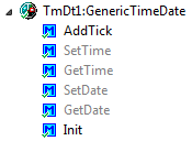
And indeed it is not that hard. Actually it took me a couple of hours, and here it is: a GenericTimeDate component which works both for the LDD and non-LDD world. I generated code with the current (non-LDD) TimeDate component, and then transformed what I needed into the GenericTimeDate component. It offers methods to set and get time and date:
The AddTick() method is called in a periodic way, e.g. from a timer. The original TimeDate component actually has a timer built in, but with my GenericTimeDate I can use whatever I want. That way I can use my RTOS tick callback as well for this:
void FRTOS1_vApplicationTickHook(void)
{
  /* Called for every RTOS tick. */
  TmDt1_AddTick();
}
The frequency of this tick timer needs to be specified in the component properties (10 ms in the example below):
The Initialization settings are used to set up date and time with some starting values.
Summary
Transforming existing non-LDD Processor Expert applications to Kinetis is not that easy, but I hope with the increased number of components with dual interfaces available things will get better. And if a component is not provided by Freescale for Kinetis, then it might not be as hard as it looks to create my own component to close that gap. In any case, I have now a Date and Time component I can use for both worlds. So it is the Time and Date to move more to Kinetis :-).
Happy Moving 🙂


Pingback: FatFs with Kinetis | MCU on Eclipse
Pingback: A Shell for the Freedom KL25Z Board | MCU on Eclipse
Pingback: Tutorial: Timer (LED) with Processor Expert for Kinetis | MCU on Eclipse
Pingback: Processor Expert Maxim I2C RTC Driver the Arduino Data Logger Shield | MCU on Eclipse
Excellent goods from you, man. I have understand your stuff previous to
and you are just extremely wonderful. I really like what you
have acquired here, really like what you’re stating and the way in which you say it. You make it enjoyable and you still take care of to keep it wise. I can’t wait to read
far more from you. This is actually a wonderful site.
LikeLike
Hi friends, its impressive article regarding teachingand completely explained,
keep it up all the time.
LikeLike
Great information. Lucky me I found your site by accident (stumbleupon).
I’ve book marked it for later!
LikeLike
I’m extremely pleased to uncover this website. I need to to thank you for your time for this wonderful read!! I definitely really liked every part of it and i also have you bookmarked to check out new stuff on your blog.
LikeLike
Hi Erich,
I found your blog very helpful. I am currently learning embedded programming from KL25Z board.
In above example, Can you explain how to get date using TmDt1_GetDate() function. I am assigning byte but its not working.
LikeLike
See https://github.com/ErichStyger/mcuoneclipse/blob/master/Examples/TWR-LL64/TWR-LL64_PE/Sources/LCD.c
LikeLike
Pingback: McuOnEclipse Components: 27-Dec-2014 Release | MCU on Eclipse