If you are new to Processor Expert in MCU10, and new to FreeRTOS, then you need to learn two new things in parallel the same time. That might be overwhelming. But don’t worry: if you do things step by step and slowly the first time, this much easier than you might think. This tutorial shall help you with this.
This is a step-by-step tutorial about how to create a project with CodeWarrior for MCU10.2, Processor Expert and the DEMOJM board. The goal is to create a project from scratch with two tasks blinking an LED. This tutorial uses the DEMOJM board, but in practice any other ColdFire/Kinetis/S08 board can be used as well.
The Board
I’m using the Freescale DEMOJM board with the S08 MC9S08JM16 CPU. This board allows swapping microcontrollers (S08JM16, S08JM60 and ColdFire V1 MCF51JM128). The board has useful components (LEDs, buttons, accelerometer, butter) and the pins of the microcontroller routed to a connector, making it a good board to connect with my own hardware.
I’m using here the MC9S08JM16 controller with 16 KByte of FLASH and 1 KByte of RAM. Sounds tiny for running it with an RTOS, but not a problem for FreeRTOS :-). The JM16 CPU has a built-in USB feature, but this is another topic with Processor Expert.
Needed Software/Tools (if not already installed)
To get things started, CodeWarrior plus additional Processor Expert components need to be installed:
- CodeWarrior for MCU10: http://www.freescale.com/cwmcu10
- FreeRTOS.PEupd Processor Expert component: http://www.steinerberg.com/EmbeddedComponents/FreeRTOS
- LED.PEupd Processor Expert component: http://www.steinerberg.com/EmbeddedComponents/LED
- Utility.PEupd Processor Expert component: http://www.steinerberg.com/EmbeddedComponents/Utility
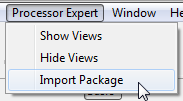
Install CodeWarrior. Then install the downloaded *.PEupd Processor Expert components using the menu Processor Expert > Import Package:
In the next dialog, select the package(s) to import:
Hint: You can select and import multiple packages in one step
Creating the project with the wizard
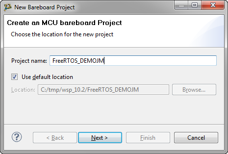
In CodeWarrior, I select the menu File > New > Bareboard Project and provide a project name:
Pressing ‘Next’. This gives me the device selection dialog:
Hint: using wildcards like *jm16 helps me to select quickly the device.
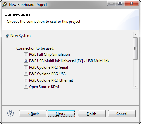
Pressing Next. This gives me the list of connection methods:
I keep the P&E USB Multilink, as this is the debug interface on board of my board.
Pressing ‘Next’. This gives a choice of programming languages:
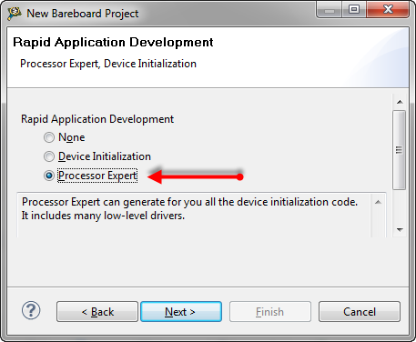
I stick with the default (C) and press ‘Next’. This gives me the opportunity to use Processor Expert:
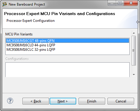
Pressing ‘Next’. Now I can select the pin variant of my processor:
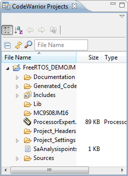
I select the QFN package on the board. Now I can press ‘Finish’, and my project gets created and shows up in the CodeWarrior Projects View:
Showing Processor Expert Views
If this is my first Processor Expert project in the workspace, then the Processor Expert views are not loaded yet. To open the views with one click, the menu Processor Expert > Show Views is used:
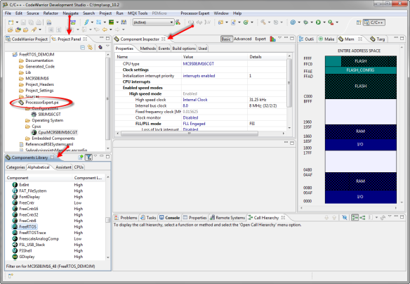
This opens a set of additional Processor Expert views:
- Project Panel View: shows the ProcessorExpert.pe which contains all the components.
- Components Library View: Lists all registered components.
- Component Inspector View: For editing the currently selected component.
Adding LEDs
Usually I need to look at the schematics of a board to see to which microcontroller pins the LED’s are connected. The nice thing with the DEMOJM board is that this is clearly labeled: PTE2 and PTE3 are used for the first two LED.
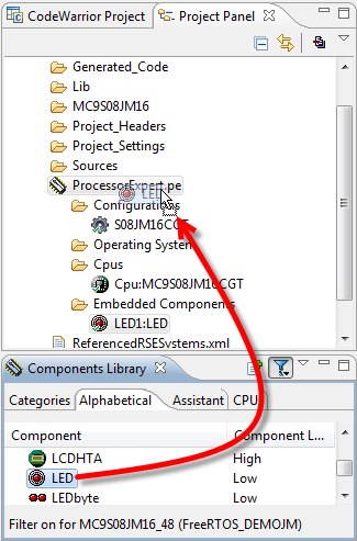
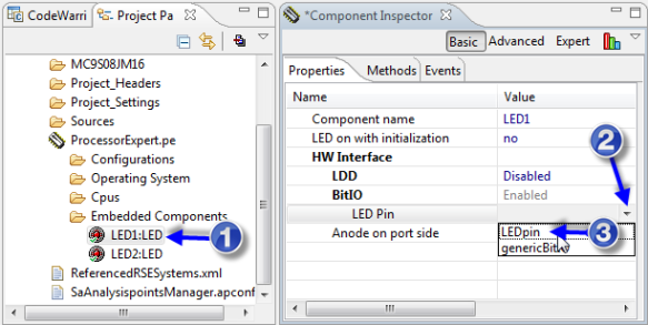
I’m going to add two LED components to my project. For this I drag&drop two LED components from the Components Library view to my Project Panel view:
I do this twice to have two LED in my project: LED1 and LED2.
To connect the LED to the microcontroller pin:
- Select the LED component
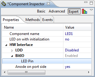
- In the Component Inspector, use the LED Pin drop down. You need to click into the field to see the drop down triangle:
Once clicked, there is a drop-down visible:
- and select LEDpin (BitIO) as interface
Note: for ARM/Kinetis, the LDD (Logical Device Driver) HW Interface is used. This is not explained here, as very different. Guess I need to write another tutorial for Kinetis 😉
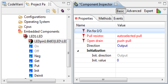
With this interface added, the interface needs to have some additional information (properties marked in red color):
I need to select PTE2 as pin for my first LED:
Doing the same thing to assign PTE3 to LED2:
Adding FreeRTOS
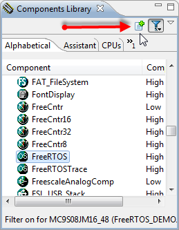
I could add the same way the FreeRTOS to the project. Or I select the component and use the ‘+’ icon:
Doing this will show the following dialog:
The FreeRTOS component is using a shared Utility component, and as we do not have added it yet, it asks to create a new one. Clicking OK will add both the FreeRTOS and the Utility:
RTOS Software Interrupt Vector
Again, the FreeRTOS component needs some additional settings. Unfolding the component shows that the software interrupt vector needs to be configured:
The operating system needs an interrupt vector for so called ‘system calls’: the way how the RTOS can raise an interrupt to initiate a context switch or similar things. This is typically done with a software interrupt instruction or a trap instruction. For the S08 core this is done with the SWI (Software Interrupt) assembly instruction.
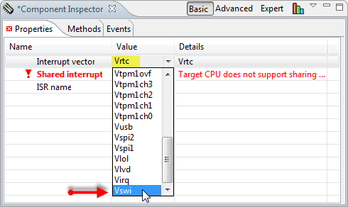
I need to configure the vector to use the one used for the software interrupt instruction, which is the ‘swi’ vector on the S08 core:
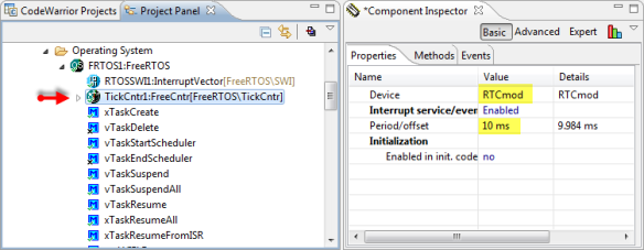
The other thing the RTOS needs is the tick counter: If needed, I can change here the timer device and the period (which is by default 10 ms):
RTOS Tick Counter/Timer
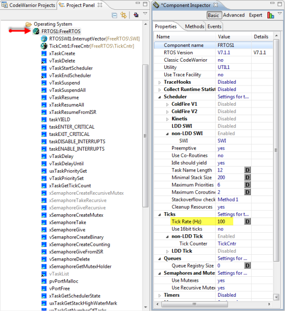
In case I change the timer tick rate, I need to tell the RTOS the changed Tick Rate Frequency:
I have not found an elegant way in the component to automatically change the RTOS Tick Rate (Hz) based on the timer frequency. So it is not ideal to have the setting in two places, but this is how it works right now.
For the S08 core the SWI interrupt settings are simple: there is only one vector possible.
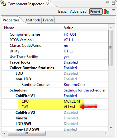
If I would use the ColdFire MCF51JM128 with my board, then the Processor Expert FreeRTOS component would recognize the V1 core being used, and enable the ColdFire V1 settings. As the interrupt settings differ from family to family, and multiple vectors are possible, I have a choice of different vectors:
In the RTOS component I need to specify the CPU family and the interrupt vector used:
Time to go back to the S08JM16 now…
CPU Stack Size
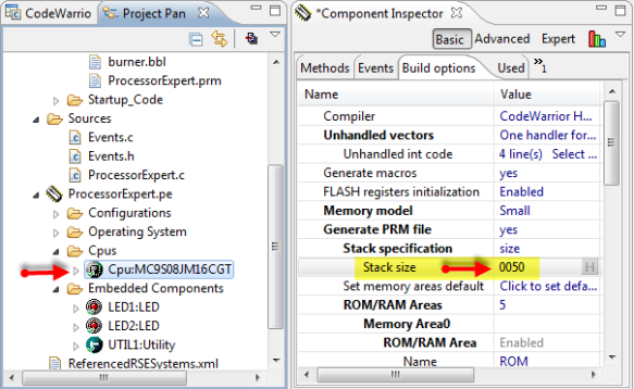
We are using a tiny S08JM16 with only 1 KByte of RAM. Processor Expert is generating as well the linker file which has an allocation for the stack. By default this is 0x80 (128 bytes) for the S08JM16. But as we are using a separate stack for each RTOS task, I need less. I reduce the stack size needed for this in the Processor Expert settings. The settings are in the CPU component, Build Options tab:
I have set to 0x50 in this project. This has to be enough for:
- Startup code (__startup(), initializing memory after reset).
- Calling main().
- Everything I do in main(), including interrupts. Note that I will create tasks in main() and start the scheduler.
Hint: how to know how much stack is needed? I use a very simple method: I allocate initially enough stack, then while debugging I write a pattern (e.g. 0xFF) into the stack area using the Memory View. Then I execute my code and immediately see what is changed in memory. This plus a margin of say 10% is then my number.
Task Default Stack Size
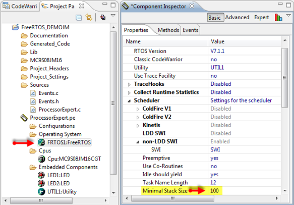
The other thing to think about is how much stack size I want to use by default for each task. This is configured in the RTOS properties:
I have it changed here to 100 as this should be enough for my tiny application.
Note: the ‘minimal stack size’ is using ‘stack units’ as entity. For the S08 core this is a byte, so ‘100’ means ‘100 bytes’. But for other architectures (e.g. ColdFire or Kintetis/ARM) a stack entry is 4 bytes, so then ‘100’ means really ‘400 bytes’.
The generated code will use that value for the macro configMINIMAL_STACK_SIZE which I can use in my code. That minimal stack size is used for the FreeRTOS IDLE Task, so should be chosen carefully. But it is possible at run-time to spend more stack for the user tasks at task creation time.
Note: Keep in mind that for architectures *not* having a separate stack for the interrupts (like the S08), the stack size should be large enough as well for the interrupts happening at the task execution time. Many weird problems are caused by stack overflows. FreeRTOS has ways to detect stack overflows, but in any doubt it is a good practice to increase the stack size in case of problems to see if this solves a problem.
FreeRTOS Heap Size
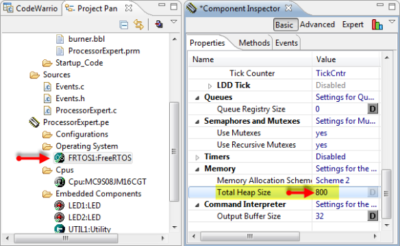
FreeRTOS is using a dynamic heap for task stacks and descriptors. That heap is used as well for other RTOS infrastructure like queues and semaphores. As my microcontroller used only has 1 KByte of RAM, I set it to 800 bytes (which leaves 200 bytes for other global variables and system stack):
Saving Processor Expert Settings
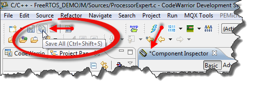
Unsaved Processor Expert settings are indicated with a ‘*’ in the Component Inspector. To save the settings, I press CTRL-S (for Save) or use the Save All toolbar icon:
Generating Code
Now it is time to generate code with our components. An easy way to generate code is
- Select the .pe file
- Press the ‘generate code’ toolbar icon in the Project Panel View
Progress of code generation is reported with progress information:
Additionally status information is shown in the Console View:
Inspecting Generated Code and Documentation
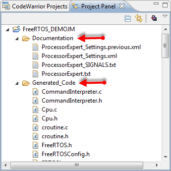
The generated code and documentation is placed into two special folders inside the project:
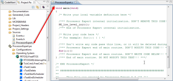
It has generated as well a file ProcessorExpert.c which contains the main() (see Disable my Code Generation for more details):
Adding Two Tasks
Tasks in FreeRTOS are easy to implement. Below is the source code for two tasks which blink one LED each. To delay the task for a specific time the RTOS API function vTaskDelay() is used:
static portTASK_FUNCTION(Task1, pvParameters) {
(void)pvParameters; /* ignore unused parameter */
for(;;) {
LED1_Neg(); /* toggle LED */
FRTOS1_vTaskDelay(100/portTICK_RATE_MS); /* wait for 100 ms */
} /* for */
}

static portTASK_FUNCTION(Task2, pvParameters) {
(void)pvParameters; /* ignore unused parameter */
for(;;) {
LED2_Neg(); /* toggle LED */
FRTOS1_vTaskDelay(500/portTICK_RATE_MS); /* wait for 500 ms */
} /* for */
}
An easy place for this is to add the above code just above main().
Note: FRTOS1_vTaskDelay() is a simple wrapper (a define) to the vTaskDelay() function. You can use both versions as they are the same.
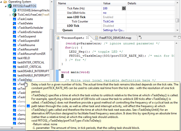
If I want to know more about an RTOS API function, I hover the mouse over the method:
Tip: I can drag&drop the method from the Project Panel view into the source file: that saves me a lot of typing.
Inside main() I need to create the two tasks, plus starting the scheduler:
(void)FRTOS1_xTaskCreate(Task1, (signed portCHAR *)"Task1", configMINIMAL_STACK_SIZE, NULL, tskIDLE_PRIORITY, NULL);
(void)FRTOS1_xTaskCreate(Task2, (signed portCHAR *)"Task2", configMINIMAL_STACK_SIZE, NULL, tskIDLE_PRIORITY, NULL);
FRTOS1_vTaskStartScheduler();
This creates two tasks (Task1 and Task2) using xTaskCreate() with following arguments:
- Task function name (Task1)
- Task name for debugging (“Task1”)
- Task stack size: configMINIMAL_STACK_SIZE
- Task startup argument: NULL for none
- Task initial priority (tskIDLE_PRIORITY)
- Pointer to task handle (NULL for none)
With vTaskStartScheduler() the RTOS scheduler will create an additional internal IDLE task and then run the RTOS.
Here is now how the code looks like for the whole source file:
/** ###################################################################
**     Filename    : ProcessorExpert.c
**     Project     : ProcessorExpert
**     Processor   : MC9S08JM16CGT
**     Version     : Driver 01.12
**     Compiler    : CodeWarrior HCS08 C Compiler
**     Date/Time   : 2012-06-27, 18:19, # CodeGen: 0
**     Abstract    :
**         Main module.
**         This module contains user's application code.
**     Settings    :
**     Contents    :
**         No public methods
**
** ###################################################################*/
/* MODULE ProcessorExpert */

/* Including needed modules to compile this module/procedure */
#include "Cpu.h"
#include "Events.h"
#include "LED1.h"
#include "LEDpin1.h"
#include "LED2.h"
#include "LEDpin2.h"
#include "FRTOS1.h"
#include "RTOSSWI1.h"
#include "TickCntr1.h"
#include "UTIL1.h"
/* Include shared modules, which are used for whole project */
#include "PE_Types.h"
#include "PE_Error.h"
#include "PE_Const.h"
#include "IO_Map.h"

/* User includes (#include below this line is not maintained by Processor Expert) */
static portTASK_FUNCTION(Task1, pvParameters) {
(void)pvParameters; /* ignore unused parameter */
for(;;) {
LED1_Neg(); /* toggle LED */
FRTOS1_vTaskDelay(100/portTICK_RATE_MS); /* wait for 100 ms */
} /* for */
}

static portTASK_FUNCTION(Task2, pvParameters) {
(void)pvParameters; /* ignore unused parameter */
for(;;) {
LED2_Neg(); /* toggle LED */
FRTOS1_vTaskDelay(500/portTICK_RATE_MS); /* wait for 500 ms */
} /* for */
}

void main(void)
{
/* Write your local variable definition here */

/*** Processor Expert internal initialization. DON'T REMOVE THIS CODE!!! ***/
PE_low_level_init();
/*** End of Processor Expert internal initialization.                    ***/

/* Write your code here */
(void)FRTOS1_xTaskCreate(Task1, (signed portCHAR *)"Task1", configMINIMAL_STACK_SIZE, NULL, tskIDLE_PRIORITY, NULL);
(void)FRTOS1_xTaskCreate(Task2, (signed portCHAR *)"Task2", configMINIMAL_STACK_SIZE, NULL, tskIDLE_PRIORITY, NULL);
FRTOS1_vTaskStartScheduler();

/*** Don't write any code pass this line, or it will be deleted during code generation. ***/
/*** Processor Expert end of main routine. DON'T MODIFY THIS CODE!!! ***/
for(;;){}
/*** Processor Expert end of main routine. DON'T WRITE CODE BELOW!!! ***/
} /*** End of main routine. DO NOT MODIFY THIS TEXT!!! ***/

/* END ProcessorExpert */
/*
** ###################################################################
**
**     This file was created by Processor Expert 5.3 [05.01]
**     for the Freescale HCS08 series of microcontrollers.
**
** ###################################################################
*/
Building the Application
I use select the project in the Project Panel view and use the menu Project > Build Project to compile and link it. This should pass without errors and warnings.
Downloading and Debugging
Finally, time to run it. For this again I have the project folder selected and use the menu Run > Debug. Running the application, and now I should see my two LED’s blinking :-).
Summary
Adding an RTOS to a microcontroller application is usually not easy. If I do not have an example for my board and microcontroller, then this can get time consuming and complicated. With Processor Expert and the FreeRTOS component I have a graphical UI to configure all the important settings (stack, heap, software interrupt and tick timer). And because Processor Expert generates all the RTOS source files and configuration files for me, this makes it really simple and easy.
Further Information…
As a starter, I suggest to have a look Quickstart for Processor Expert in Eclipse. This gives a head start on some aspects of using Processor Expert.
For more information about FreeRTOS and the API, have a look at the FreeRTOS documentation on the web.
Happy FreeRTOSing with Processor Expert 🙂














Pingback: CDE Hacking: Where is my stuff? A dissection… | MCU on Eclipse
Trying to follow through as close as I can, using my own MC9S08AC128 board, all is good until I to to select the LED Pin – there is no dropdown or other means to select one. Is there some setting dependency, so there is something I should have done before adding the LED component?
LikeLike
Is LDD disabled and BitIO enabled? I see that what you see is a possible UI glitch: unless you click into the field, there is no drop down icon visible :-(. I have not realized that before. I’ll extend the post so hopefully this is more clear.
LikeLike
Yes – out of the box, LDD is disabled, BitIO is enabled. If I click the value column for LED Pin, I get an error, due to the pin being unassigned. So I go back to Project Panel, expand LED1:LED, go to LEDpin1:BitIIO, then select the pin I require in properties, and all is good. Yes, I didn’t realise I had to click into that field. Now I just have to check my schematic to find what pin the LED is actually attached to!
LikeLike
Yes, I have reported that UI problem to the Processor Expert team. It looks like having the drop down box not visible unless you click into it is a problem of the underlying Eclipse UI control they are using. Hopefully this will get fixed/improved in a next version.
LikeLike
HI, thank you for your tutorial. I try use FreeRTOS component, but I can’t. The program always stop on “void FRTOS1_vApplicationMallocFailedHook(void)”. I use a MCF51JM128.
LikeLike
Hello,
This means you have not enough heap allocated. Try to increase the heap size in the properties. Hope this helps,
Erich
LikeLike
Hi, heap size of CPU or FreeRTOS? thank you.
LikeLike
Hello,
The heap size of FreeRTOS.
Hope this helps,
Erich
LikeLike
Great Post! I’ve been trying to get into the FreeRTOS with freescale for a long time until yesterday that i found this post on google. Thank you!
LikeLike
Cool! Glad to see that this is useful.
LikeLike
Pingback: Tutorial: Freedom with FreeRTOS and Kinetis-L | MCU on Eclipse
This looks very good, and so I am tempted to try to do this on Kinetis. Erich, do you have anything on the Kinetis and FreeRTOS?
I have to use the FlexTimer and it is very hard to implement into MQX. The project keeps trapping into the Kernel. I can get the system to work without mqx using device init, but not with mqx. Do you know if it easy or hard to use FreeRTOS and Device Init to run the FTM? I don’t need a driver, I can do all the bit banging for the registers, my problem is this mess with MQX and the integration of the code from Device Init.. because PE is not properly integrated as yet with MQX.
Thanks
Robert
LikeLike
Yes, there is a tutorial for this: https://mcuoneclipse.wordpress.com/2012/09/29/tutorial-freedom-with-freertos-and-kinetis-l/
It is mainly for Kinetis L, but applicable for K family too.
LikeLike
Hello,
Thank you for this great tutorial. I tried it on my S08JM60 and FreeRTOS opened new horizons to me 🙂 But there is (as always) a problem. I Tried to implement some basic “Process UART Data Buffer” and “Display received Data” tasks. Data buffer is filling up in SCI Rx Interrupt routine. The problem occurs when there is lot of data transfered (115 200 baud rate). Some bytes are missed in communication, and i was able to track the reason to UART “overrun” error. It is heading me to the problem of interrupts priorities. I think that SWI interrupt is taking too long to switch contexts, and doesn’t leave enough time to SCI Rx interrupt to process received data, so overrun occurs. Is there any way to change the priorities so sci interrupt is not missed anymore? Or I am missing some other point there? If you have anything on mind that could possibly help me, please let me know. Thanks in advance. R.
LikeLike
Hello,
I think the answer would depend on your continuous data rate. What I have used successfully is using the AsynchroSerial Processor Expert component in interrupt mode. That component has a built-in internal buffer. I have set that buffer to a size matching my incoming traffic and depending on my overall latency time. That buffer (say 1 KByte) is filled up within the interrupt routine, while I have a FreeRTOS task to read it out. In my application I storing that serial data to a SD card memory. The bottle neck was usually the SD card interface. Apart of this, profiling your application timing might help. I’m using the FreeRTOS+Trace (I wrote a post on this) for this: that way I see the execution pattern of my application and can tune it to my needs. I hope this helps.
LikeLike
Thank you for this great tutorial. I tried it on my S08JM60 and FreeRTOS, i’m using DEMOJM but it’s example does not work, how to configure FreeRTOS heap size, CPU Stack Size and Task Default Stack Size?. Thanks.
LikeLike
Hi Alexander,
the ‘CPU stack size’ is configured in the CPU component/build options. The heap size and task default stack size is configured in the FreeRTOS component itself.
I hope this helps, otherwise I’ll publish an example for the S08JM60 on GitHub.
LikeLike
Hi Alexander,
hmm, I have indeed found a problem in the S08 port introduced with the latest RTOS version (tickless idle mode support) :-(. I believe I have fixed it, and I want to run some additional tests. I will publish as well an example project on GitHub. I’ll post another comment once I’m done. Sorry about that!
LikeLike
Hi Alexander,
I have pushed a fix on GitHub (https://github.com/ErichStyger/mcuoneclipse), together with an example project for the S08JM60 (https://github.com/ErichStyger/mcuoneclipse/tree/master/Examples).
Let me know if things are working now on your side.
LikeLike
Hi, thanks for the tutorial. Unfortunately, I’m having some trouble getting FreeRTOS tasks to run on my Coldfire V1 MCF51JM64. I followed the instructions in the tutorial, and it didn’t seem as if my tasks were running, so I tried running the same code in my main. When running this from main, I stepped into vTaskDelay(), then into uxListRemove() (from tasks.c, line 796), and then while stepping through the function, it jumps to the CPU_Interrupt upon executing the line “pxItemToRemove->pxPrevious->pxNext = pxItemToRemove->pxNext;” from list.c line 187. Could this possibly be resulting from some incorrect configuration settings, or maybe a FreeRTOS bug? Any help you could provide will be appreciated.
LikeLike
I only have the MCF51JM128. Probably I should create a demo project for it and publish it on GitHub. What version of the FreeRTOS component are you using? check the Generated_Code\FRTOS1.c file, mine has version 133:
** Date/Time : 2013-08-29, 15:39, # CodeGen: 133
LikeLike
Hi Kyle,
I have commited a demo example for the DEMOJM with the MCF51JM128 on GitHub: https://github.com/ErichStyger/mcuoneclipse/tree/master/Examples
LikeLike
Thanks for the quick reply. I appreciate you uploading the demo project, it does work on my JM64. Also, I believe that the CodeGen number that you are referring to is referring to the number of times that processor expert has generated code for the file, as it was 10 for the first project I tried running, and it is 0 for your example that I imported.
LikeLike
Hi Kyle,
good to hear that the project works now for you.
And you are right, I used the wrong number.
The component version number is something like this:
Version : Component 01.296
LikeLike
Hello, I am trying to use RTOS on MCF51JM32VLH, when I generated sources and tried to build, theree was an error in FreeRTOSConfig.h
there was
#define configCPU_FAMILY configCPU_FAMILY_V1
and then there was an error with port.c compilation – I think it was expecting
#define configCPU_FAMILY configCPU_FAMILY_CF1
after I changed it, it compiled ok and LED example is working fine on my HW.
LikeLike
Hi Martin,
ups, sorry about this. Indeed, that is wrong for ColdFire V1 (same bug for ColdFire V2). I have fixed it now on GitHub.
https://github.com/ErichStyger/mcuoneclipse/commit/aba394fb84aacd8abf0ebee770bef0aaf2355c4b
You can make the same fix on your side: Open
C:\ProgramData\Processor Expert\CWMCU_PE5_00\Drivers\freeRTOS\FreeRTOSConfig.h, and the change is around line 405.
The plan to create new PEx component on GitHub shortly, and it will of course include your fix.
Sorry about this, and thanks for reporting!
LikeLike
Thanks, that helped!
by increasing the heap size from the default 1024 to 8192 (4096 failed as well…) I got the two tasks to work together.
btw, I noticed that the program fails at the function FRTOS1_vApplicationMallocFailedHook();
It would be much helpful if in the future you will please publish a post about stacks and heaps and related issues.
Thanks again,
LikeLike
I recommend that you have a look at the FreeRTOS.org site, as this kind of information is already there, e.g. http://www.freertos.org/a00111.html
LikeLike
i tried to use this tutorial on JM32 and when i pressed build i got the following error
(Out of allocation space in segment RAM at address 0xD8)
can you please help?
LikeLike
So you are using more RAM than you have on your board. You can:
– reduce the FreeRTOS heap size
– reduce the stack allocated in the CPU component for the startup code
I hope this helps.
LikeLike
Hi. I’m trying to run your example for the JM128 but I get the following error:
“There was an error parsing the memory configuration file:
Range 0x0:0x3FD overlaps with Reserved range 0x3FC:0x3FD”
I modified 2 things:
1)Changed USB multilink to USBDM.
2)Changed CPU to JM128VHQ (64 pins)
Everything else is the same.
Any idea?
Thanks!!!
LikeLike
UPDATE: I didn’t mentioned that the program build fine, and I can flash the generated .elf file with the USBDM CFV1 flasher. The problem is if I’m running it from CW 10.6.
Thanks.
LikeLike
You need to check the .mem file inside the project (Project_settings\Debugger folder). I know that earlier versions of the tools might have created a .mem file with such an overlap. You can fix that directly in that .mem file (it is a text file).
I hope this helps.
LikeLike
Thanks Erich, it’s working now (I also had to change the heap size from 1024 to 8192).
LikeLike