In eclipse and CodeWarrior for MCU10 the usual thing I do is:
- I have a project in my eclipse workspace
- I compile and build it
- I download and flash it to the target for debugging
If I need to program another board with the same binary, then I download it to that board too. Fine. But what if I want to skip point 1 and 2? What if I do not have or want a project? All what I have (and need) is a binary file, and I want is to flash that file to my boar. By pressing a button.
No project, just the naked workspace
Eclipse is very project oriented. But with the release of MCU10.2 it is possible: I can program my boards without a project . All what I need is the binary file I want to flash. Really? Well, close. Some setup is still required.
In the following steps I’m using a new and blank workspace. The same thing can be used with projects in the workspace too. Then things are even easier as I can re-use settings. But here I’m going to do the heavy metal stuff naked, without a project, but with a Magic Wand. Actually, it is a Magic Blue Flash Bolt :-).
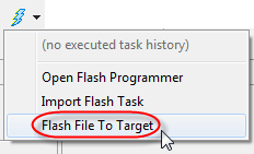
To start, I use the ‘Flash File To Target‘ menu:
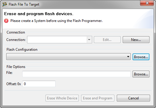
This gets me the following dialog:
Oh, and here is it: it ask to create a ‘System’….. OMG!
System, Connection, Target or what the ….?
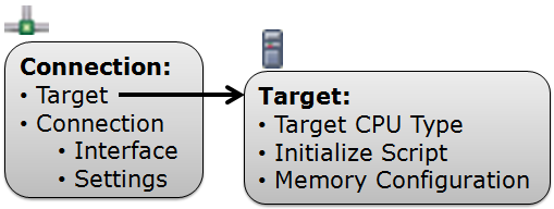
System? Yeah, that’s a very overloaded term (like many others). I would explain an MCU10 ‘System’ as a combination of ‘Connection’ and ‘Target’:
- The ‘Target‘ specifies the CPU used (e.g. MCF51JM128), with its initialization script (if any) and the memory configuration needed (if any).
- The ‘Connection‘ references a the target, plus it holds the settings how I connect to the target, with the Interface and settings for it, e.g. P&E USB Universal Multilink.
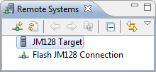
Both the Target and the Connection are listed in the Remote Systems view:
The Flash File to Target needs a Connection. So we need to create a Connection and a Target.
Creating a Connection
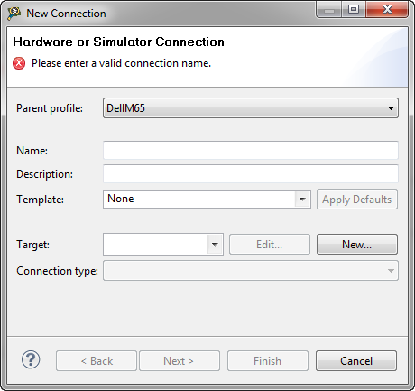
Pressing the ‘New…’ button in the Flash File to Target dialog gives me:
Ok this is the Connection. Here I can configure the connection settings, and create a new Target.
Creating the Target
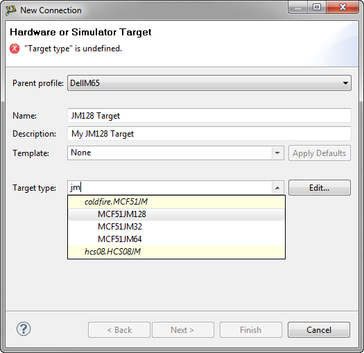
To create the ‘Target’, I’m pressing ‘New…’ in the New Connection dialog:
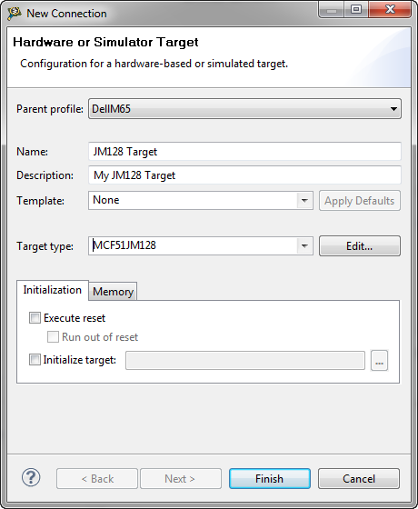
This is the Target (don’t get confused by the dialog title!!!). Ok, you are confused. But this is really the Target. Here I specify the CPU (MCF51JM128 in my case). Having this defined, it allows me to change further settings:
I do not need any Initialization or Memory configuration, so I keep these with the defaults.
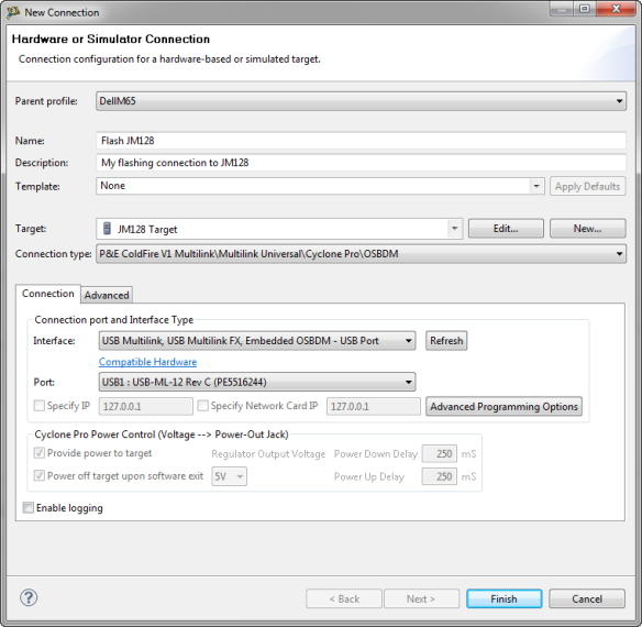
Back to the Connection dialog, I choose to use the P&E connection:
This expands the dialog for the run control specific settings:
Now I have my connection and target created from the ground up.
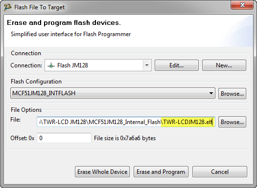
Next I’m browsing for my binary file to be programmed to the board:
The file is an ELF/Dwarf file or an S19 one.
Pressing the ‘Erase and Program’ button does what it says: it does a mass erase of my device and programs it with the file. If I need to erase/protect only part of my device, then Programming part of Flash provides the needed information.
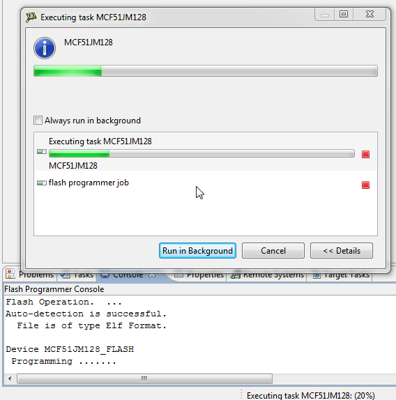
Time to wave the wand (or flash bolt): Progress is reported in a dialog window, and as well in the console view.
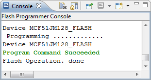
At the end, the dialog closes automatically (why? what if I would like to flash the file again?). The completion of the operation is reported in the Console view:
Dissection of what is behind
Ok, things are working. Time to check out what is behind. As there is no project, the settings have to be *somewhere*. I notice that I have an LC for Simple Flash in the list of Launch/Debug configuration:
CodeWarrior is using a pseudo ‘Connect’ configuration to store the information.
Note: While this looks like a normal ‘CodeWarrior Connect’ launch configuration, it will not work as such (if I want to use it directly), as it has no project folder associated.
This launch configuration is stored inside the workspace as a normal file:
.metadata\.plugins\org.eclipse.debug.core\.launches\LC for Simple Flash.launch
So while this is not really a normal launch configuration, it is still useful to know about it.
Summary
Using the Flash File to Target menu and button makes it really easy to flash a file to the board without the need for a project. Still, for a naked workspace, some settings are required which take a little time to set up. With knowing the things behind, no magic wand is needed, as long as it creates systems, connections, targets or whatever their names might be 😉
Happy Button Flashing 🙂



Pingback: USB CDC goes medical | MCU on Eclipse
Pingback: Standalone Flash Programmer | MCU on Eclipse
Pingback: Changing the CPU with Processor Expert | MCU on Eclipse
Pingback: Hot-Sync: Attach, Connect & Download | MCU on Eclipse
Pingback: Copy my CodeWarrior Project | MCU on Eclipse
Pingback: Unsecuring the KL25Z Freedom Board | MCU on Eclipse
Pingback: How (not) to Secure my Microcontroller | MCU on Eclipse
Just to experiment, I created a project and wrote a program to blink an LED on TWR-KL25z board. The code works fine and I see the LED blinking. Then I removed the project from my workspace and followed the steps in the post. Target is KL25z128m4 with no memory or target initialization. Connection is openSDA.
For the file to flash I chose the .elf file from the project and clicked on erase and program but I’m getting an error”Executing task KL25Z128M4 has encountered a problem” and “an internal error occured during executing task KL25Z128M4″… So can you please help in programming/button flashing?
LikeLike
Uff! I’m sorry. The problem this code warrior creates!!
I restarted the codewarrior. Now it is programming. But the new issue is I have to press the reset button after programming successfully once to start LED blinking. Any light you can throw why this is happening
LikeLike
I can confirm that if you just download, it will not reset the processor so it runs. So yes, this is an extra step.
LikeLike
Hello Erich,
I have a question Regarding Flash Button Programming.
I tried the above method to program MC9S08RN8 Freescale Controller , it is successful but the problem is the default value of Trim Register ICS_C3 and Fine Trim ICS_C4 , i am not getting correctly, i don’t know why, Here what i did
1) First i programmed controller using Debugger method , without controlling Trim register in my code and i got the Total time of PWM of 11 msec (For the PWM code which i have written using Timer) , after POR (Power on Reset) i got Total PWM time of 12 msec.I posted the question on Freescale community and got the suggestion that may be Debugger is writing the Trim Register.
2) So i added Trimming Register control code in my main code the problem is solved . The following code i added for Trim register
if ( NV_ICSTRM_INIT != 0xFFU) { // 0xFF6FU Test if the device trim value is stored on the specified address
// ICS_C3 = *(uint8_t*)0xFF6FU; // Initialise ICS_C3 register from a non volatile memory
// ICS_C4 = (uint8_t)((*(uint8_t*)0xFF6EU) & (uint8_t)0x01U); // Initialise ICS_C4 register from a non volatile memory
ICS_C3 = NV_ICSTRM_INIT;
ICS_C4 = ((NV_FTRIM_INIT) & 0x01U); // Trim the internal clock :((NV_FTRIM_INIT) & 0x01U);
}
After adding the above Trim register control code i got the same PWM Total timiming of 11msec before and after the Power on Reset.
3) Actually i wanted to program the controller without Trim register control code so i used your method , but with your code also i am getting the Total PWM timing of 12msec with and without Trim Register Control code.
can you please suggest me do i need that Trim register control code or not in both the programming cases and Which method is correct for programming on Timing delay point of view?
Thanks and Kind Regards,
Robin
LikeLike
I am using µC MC9S08RN8
LikeLike
Hi Robin,
I have not checked your device, but from what I can tell is that the TRIM values are loaded from a special location in FLASH and then stored in a RAM register.
If so, then you need to make sure that these values are copied from FLASH to RAM at runtime (in your application). It looks like you are doing that (with the copy from 0xFF6F). This means that you need in your application the flash programmed at that location with the value you need.
Erich
LikeLike
Danke Schön Erich.
LikeLike
Hello Erich,
one more Question:- Why trimming value with flash button programming is 31250 hz instant of 39062 hz which is factory trim value, even though i am not changing the trim value in “RUN CONFIGURATION” ?
can i see somewhere µC Bus frequency while programing using flash button , like in Debugger programming it shows me in console.
I am using Codewarrior 10.5
µC : MC9S08RN8
Progrommer : PE Micro USB Multilink
Thanks and Kind regards,
Robin
LikeLike
I’m not sure, but I would say that this value comes from the run configuration which you have selected for the flash button programming.
LikeLike
Respected sir
I have question related to flash code in XBEE SMT module have MC9S08QE32 microcontroller.
Sir, ‘Flash File To Target‘ menu can not be show in Code warrior 10.2 with XBEE SDK.
I have use directly use sample code of give in CodeWarrior 10.2 with XBEE SDK . I am select “Xbee sample application project ” in that next select my device Xbee 865/868 lp S8 module next i have have to select GPIOs project in that i have select blink_led project. Then i have to build that project. After that i have go to run configure then in connection type i have select “P & E HSS08 Multilink \ Multilink Universal \ Cyclone Pro \ OSBDM ” then i run that project but i got “POWER CYCLE DIALOG” after click ok then i get this window “p&e connection ” .
please give me solution of my problem.
LikeLike
Hello,
CodeWarrior 10.2 is very, very old. The current version is 10.6. It could be that this menu item has been added later, so I highly recommend that you move to version 10.6.
LikeLike
I also think so but when i am doing changes in trim frequency for run configuration for selected flash it’s not taking the changed trimmed value, don’t know why?
LikeLike
Pingback: Unlocking and Erasing FLASH with Segger J-Link | MCU on Eclipse
Pingback: Tutorial: How to Erase the FLASH with the GNU debugger | MCU on Eclipse
Hey, I have a task to make a stand-alone programmer which will program the target controller without needing to be connected to PC. Just with press of a push-button. Can you tell me if you have done that ? PC should not be connected to programmer after it has the target code fed in it. USBDM is supposed to do that. But i am unaware of how the bootloader works and how will it program without PC. Please help
LikeLike
The programmer will need some local memory for this. What you are asking for is e.g. supported with the P&E Cyclone (www.pemicro.com). Products from Segger (www.segger.com) can do this as well. Otherwise you need to modify the USBDM firmware, add an SD card or similar to it. USBDM needs a PC connected to the programmer afaik.
LikeLike
Thanks a lot for quick reply but Cyclone costs 900$. We dont have that much finance. Besides, you must have heard about USBDM, it is said that USBDM supports stand-alone programming. But i havent seen any project showing it. I need help regarding it.
LikeLike
It depends what you understand under ‘standalone programming’: typically this means that you do not need an IDE/Debugger to program the device, but can use a small program on the host PC. USBDM does that, as well gdb (see https://mcuoneclipse.com/2015/03/25/command-line-programming-and-debugging-with-gdb/) with P&E, Segger and OpenOCD.
LikeLike
So, you mean to say that there is no way that one can program without the help of PC using USBDM ? My supervisor thinks that USBDM will make the programmer free of PC connection
LikeLike
I’m not aware of such a way with USBDM. In any case, you will need some dedicated hardware to store the image you want to flash (e.g. on a SD card, internal memory of the device or a flash card). This is exactly what the Cyclone has, and what it is used for: for production type programming.
Another thing you need to consider: for production programming you should not use ‘debugger’ programming like what is used in debuggers like USBDM/etc: if you want to be sure that the FLASH is programmed according to the specs so it lasts for the time in the specs, make sure you are using a certified programmer for it. That’s where the price point of professional solutions like P&E Cyclonce comes into the play. It all depends on your business model: if you are making money with your products, you probably have to think about having the right investment into your equipment? Just my 1 cent.
LikeLike
Hi Eric
I did downloaded .elf file from project, but board is not running(checking for led to blink) after download succeeded,please find the log from console is below
I disconnectAuto-detection is successful.
File is of type Elf Format.
Downloading 0x00000198 bytes to be programmed at 0x00000000
Executing program ….
Program Command Succeeded
Downloading 0x00004DD0 bytes to be programmed at 0x00000400
Executing program ….
Program Command Succeeded
I tried recycling the power to board, sill doesnt work.
If I run it has debugger same code works time.
any idea what i am missing
thanks
Niranjan
LikeLike
Hi Niranjan,
does it work if you download it with the debugger?
Erich
LikeLike
Yes it works when I download it has Debugger, I mean when I hit “Debug” on Codewarrior
LikeLike
Hmm, strange. I guess you have to compare the two binaries to find out what is different. You can dump the memory and then compare it, see https://mcuoneclipse.com/2012/05/04/dump-my-device-memory/
LikeLike
Hi Erich!, do you know how to flash via “flash file to target” and codewarrior manage the trim value?. The only way that i found to do this is via debug, but it´s not really confortable if i have to flash more than one mcu!.
Thank you!
LikeLike
To my knowledge, normal flashing does not change/affect the trim value.
LikeLike
That´s my problem!
I´d like to OSBDM to calculate trim value and program the non volatile registers, but codewarrior doesn´t do that when I use “flash file to target”.
It only does if I program the mcu via the debugger (I think it uses some P&E soft in that case instead of the codewarrior programmer).
You are the master!, any idea that can help?
Thank you!
LikeLike
Is your target the S08? I have not used that part for years.
‘Flash file to target’ uses a different way than the normal debug way (I think for historical reasons).
If you are serious about production programming, I recommend to buy a professional gang programmer (Cyclone, etc) (yes, it costs money).
Otherwise: have you tried this: https://mcuoneclipse.com/2012/08/03/codewarrior-flash-programming-from-a-dos-shell/
LikeLike