
Summer finally has arrived in Switzerland. Yes, I live in a moderate climate zone, but if the outside temperature goes above 28-30° Celsius as these days, then sleeping at night is not that comfortable as it should be in my view. Luckily, I’m in a good constructed house with good insulation, so it takes a few days until it heats up. But I love to keep the temperature below 25° Celsius, especially at night. I do have a heating system which combines geothermal and solar heating. The question is: how can I use it for cooling during hot summer days? The solution: some extra plumbing, a Freescale Tower system and the Freescale FRDM-KL25Z board 🙂

FRDM-KL25Z with Arduino Data Logger Shield controlling Heating/Cooling System
❗ Warning and Disclaimer! Serious mechanical, electrical, electronic and software engineering skills are needed if you want to do something like this. Be aware that the thermal and electrical power used in this project can dangerous. Do it at your own risk! And there is no guarantee what worked for me will work for you. I conducted this project with the professional tips of my colleagues at the University of Lucerne for Applied Sciences and Arts (Thermal Energy Systems and Process Engineering), and if you do not have the expertise or knowledge, you better do not start such a project ;-).
Ending the Oil Burning Area
Last year, my old heating system based on burning oil started to need increased maintenance. The same time the oil prices were going higher and higher. So the idea was to replace the old system and replace it with a more CO2 neutral solution, especially as the government in Switzerland offers tax and funding incentives. So we decided to get rid of the oil tanks and oil burning system, and replace it with a geothermal plus solar heating system. Of course such a project needs a lot of administrative work to get all the required permissions (environment safety, construction regulations, etc). But finally I had all the paperwork done, it was time to actually get some work done :-)….

The old heating system ripped out
Geothermal Drilling
The first phase was to drill a 186 meter hole into the ground. Geothermal drilling and heating are getting a standard. But to me that drilling machine was still impressive, and I was thinking that maybe in my next life I should be a mechanical engineer ;-):
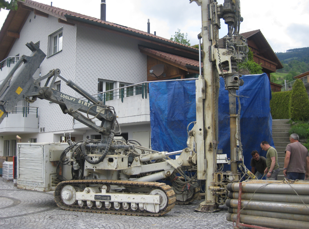
Geothermal Drilling Machine
The drilling machine needs a big compressor for high pressure water supply:

Water Supply Compressor
As the underground was special and the area is on an old landslide area, the first 50 meters required special pipes to avoid the drill hole to collapse. So outside of the drilling head another pipe with larger diameter gets installed:

Pipe Depot for the first meters
The water is pressed into the drilling hole both to cool the drilling head plus to get drilling material out of the hole:

Drilling the hole
Adding a new pipe is fast and efficient, so the drilling took only two days:
The water with the drilled material gets collected in a container:

Collecting the drilling water
Regularly, the container (two were installed in parallel) needed to be drained by a big pump truck:

Pump Truck

Pumping the water out
But around 23 meters, the drill master was swearing about something strange was going on. And indeed, in the drill water container something strange showed up: pieces of wood!

Drilling Wood?
So this confirmed that we are on an old land slide area: we hit with the drill machine a more than 7000 year old cedar tree!
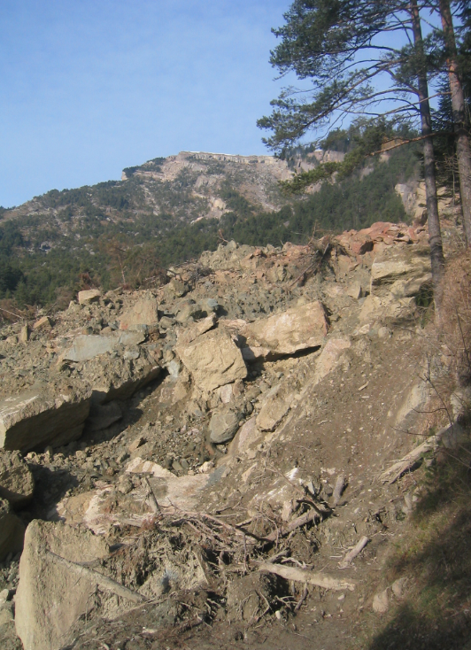
Goldauer Rock Slide from 1806
That tree got buried in a pre-historical rock and landslide after the ice age. When the glaciers retrieved after the last ice age it has caused several land and rock slides in the area. The most recent is from 1806 which buried the Goldau village nearby:

Goldauer Rockslide Area
Every 20-50 meter there is a layer of marl which gets slippery if in contact with water. This layering is clearly visible in the top rock slide area. And the rainy and wet summer of 1806 caused that big rock slide, and killed 457 people (see Goldauer Bergsturz):

Goldauer Rockslide Starting Point
The area still has not stabilized yet, as shown by a smaller landslide event back in November 2005:
Landslide from 2005

Landslide 2005 at ‘Gribsch’
So I keep fingers crossed that it keeps stable for the next few hundred years ;-).
Underground Profile
Back to drilling :-).Because that area is of interest for any geologists, I had to collect a sample every meter of drilling. Based on this, a detailed underground profile is the result:
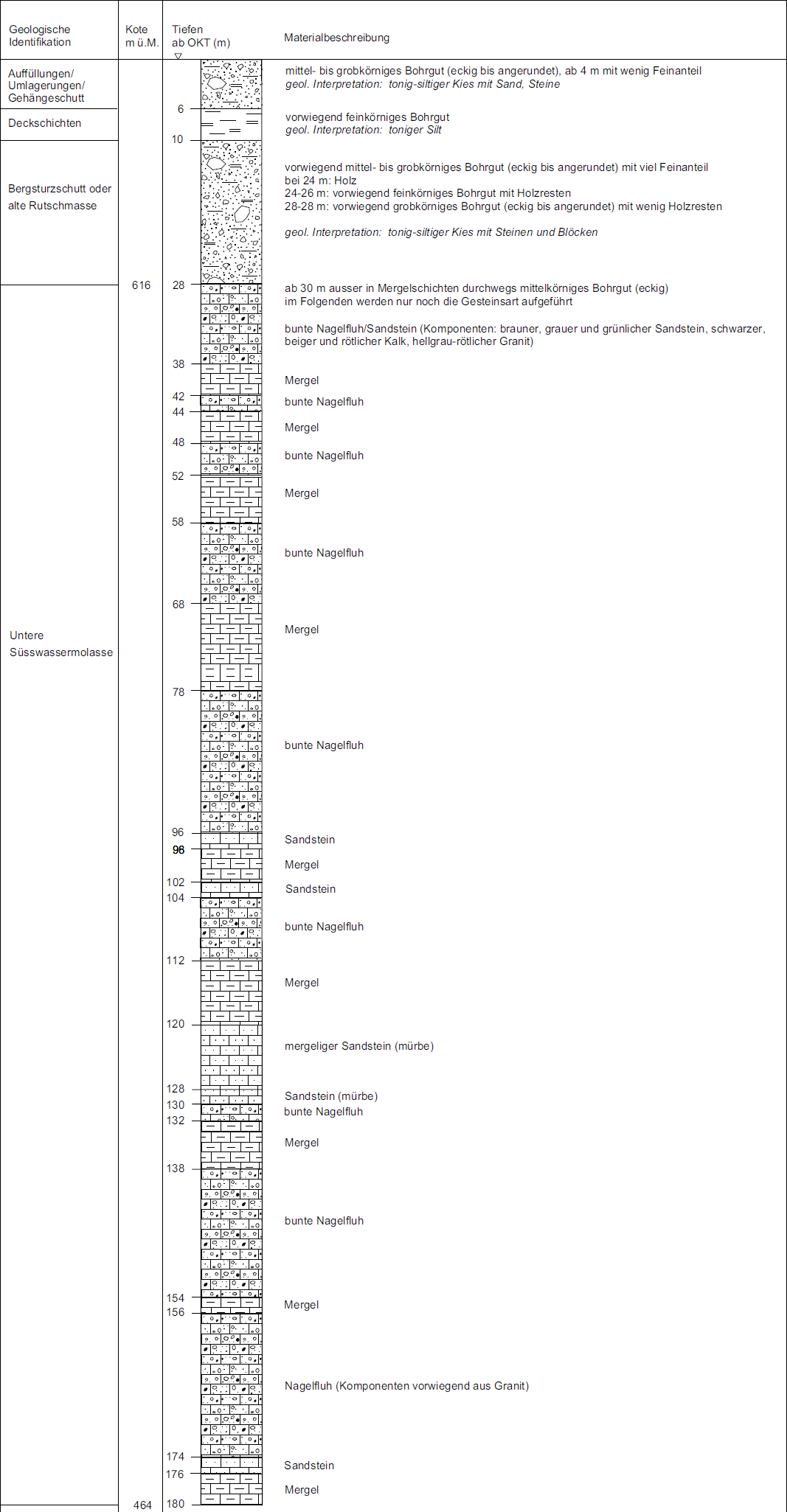
Underground Profile
To bad: no treasures found ;-). And drilling was down to 180 meters.
Back-Filling the Drilling Hole
To get the geothermal heat, a special fluid will be circulating in the hole. For this, two U-Shaped pipes (4 single pipes in total) get installed:

U-Shaped Fluid Pipe (end at the bottom)
Two such U-shaped pipes get combined with a heavy metal piece at the bottom:

Heavy End Piece
Tied together, the pipes are ready to be put down:

Fluid Pipes Prepared
With the help of the metal weight, the weight of water filled in the pipes and air pressure everything was pulled down with minor issues:

Pushing the pipes into the drilling hole
An extra pipe is added to the two U-Pipes, it is used later for backfilling the hole from the bottom with mortar:

Two U-Pipes plus Backfill Pipe
Pushing things down worked for the first 52 meters. Then things were stuck:

Stuck at 52 Meters
Because the drilling hole was filled with water, this created enough up-pressure that the pipe did not go down further. To counter this, the pipes were flushed and filled with water. With a lot of water to get any air out of the system. This increased the weight of the tubes to get them down 100 more meters:

Filling Pipes with Water to increase Weight
Still 30 meters to go! But things are stuck again. The problem is the pressure down at 150 meters, plus the friction of the pipes in the hole. What remains is a rather risky procedure: to blow pressurized air into the backfilling pipe to get the water out of the bottom of the hole. This would remove the counter pressure from the bottom, but the same time the risk is that due the reduced pressure it is possible that the hole will collapse :-(. But there is not much else you can do, so we agreed on taking the risk. With the compressor pressurized air is put into the hole, pushing the water out of the drilling hole:

Pressurized air to push out water
With this, we made the last 30 meters without issues :-).
At the end, this is what remains on top is this:

Pipes Installed
The drilling hole gets backfilled with mortar: for this, a 5th tube has been put down so the hole can be filled from the bottom up. The mortar gets mixed with water and pumped down:

Filling Mortar
Instead of using the normal mortar to fill the drilling hole, I used a special one with better heat transmission value (2.32 W/(m-K)) instead of the normal 1 W/(m-K):

Special Mortar
💡 Higher W/(m-K) eases the energy flow from/to the geothermal probe with the surrounding rock.
At the end, everything gets put into the ground and into the building. Both U-shaped pipes get combined into a larger one:

Pipes into the building
Heat Pump
The pipes end up at the head pump which stores the energy inside a water buffer:

Heat Pump with Buffer (plumbing not insulated yet)
In addition, 12 thermal solar panels supply energy to the system:

Thermal Solar Panels
The solar panels are about 30 m2 and can give enough energy during summer time (actually too much). And they help the heating system during winter time. If the sun shines on a winter day, I get enough energy for 2-3 days. It was not possible to put the panels on the house roof: the house roof is East-West oriented, so not possible to place the panels facing south. Plus the angle would have been too flat: at wintertime the sun is pass low on the sky, so having the panels more vertically oriented with an angle of 70-80° is ideal for such a heating-aid system.
Cooling
So far this is all about heating. So where is the cooling part? The basic idea is to use the underground as an extended buffer to store the not needed heat during summer time. So the geothermal probe is used to get energy during winter time, and to store energy during summer time. There are two sources of exceed heat which can be used:
- Solar Energy: During a sunny summer day, the thermal solar panels produce up to 90 kWh a day, far mor than it is consumed. If it would be sunny during several days, the system would stagnate because of overheating. While the system can deal with stagnation, it is not good in general because of the high temperature in side the solar panels. So the idea is instead the system to allow to go into stagnation, using a predictable controller which pumps the extra energy into the ground.
- Cooling the building: In hot summer time, the building is heating up above 25° C, while the geothermal probe temperature is around 12° C. I have a low temperature floor heating system, so the idea is to make a ‘free cooling’ system where the fluid in the floor heating system is cooled by the lower temperature of the ground.
💡 In addition, I’m using a small outdoor pool with the extra energy available during summer time.
Everything is still somewhat experimental, but to deal with the above two cases, I installed
- Cooling Heat Exchanger between the buffer/floor system and the geothermal flow.
- Floor Cooling Mixing Valve to control the floor cooling temperature. I need to make sure that the temperature does not go into the condensation state.
- Buffer Cooling Mixing Valve to limit the temperature going into the geothermal/cooling heat exchanger from the buffer. I’m using PE as geothermal pipe, and although PE is stable up to 60-80° C, I want to limit the heat going into the pipe.
- Cooling/Heating Switch which turns either cooling or heating on. It has an extra helping relays which is used by the controller.

Cooling System Parts
The schematics below shows the hydraulic system:

Heating and Cooling System Block Diagram
I measure temperature and pressure with Grundfos Digital Direct Sensors:

Grundfos Direct Sensors
Sensors and actuators are managed by a control system based on Freescale Tower Modules, more about this later. As backup (I did not expect my control system to work right away 😉 a normal Resol solar controller is used).

Final Plumbing with Insulation
Hacking the Hoval Heat Pump
The problem is that by default the Hoval heat pump used is not ready for such a cooling functionality, and the internal controller is not able to easily handle this. After going back and forward on different solutions, I decided to hack the pump electronics for my needs. All what I need is to make sure that the pump is not turning on the compressor, plus I need to turn on the circulation pump of the geothermal system.
For this I internally switch off the heating (and compressor system), and I’m misusing an internal maintenance mode which is used to flush the geothermal system. This mode is accessible using the ‘Manual’ mode button on the control panel:

Manual Mode Button on Hoval Toptronic
To control that button plus the pump, I’m going to modify the heat pump system and adding a FRDM-KL25Z to do all the needed internal controls.
First, to open the heat pump system to get access to the backside of the control panel:

Open Heat Pump with Backside of Control Panel
The first thing is: I need to rewire the pump and valves from the heat pump to my control system: for this I have them detached from the Hoval control board and wired it to my control system. It looks messier than it is :-):

Rewiring the Pump Power Control
To control the Hoval heat pump from my control system, I had to detach the panel and to remove the back cover:

Hoval Control Panel with Cover removed
Then need to identify the push button on the front side of the panel:

Front Side of the Panel with Button
Two wires get soldered to the ‘manual’ push button:

Wires soldered to push button
The wires get to the backside of the panel:

Wires to the backside of the panel
The wires plus the wires for the pump are attached to a relay print. I’m using a dual channel opto-isolated relay print from YourDuino. As 230V AC are involved, everything is put into a plastic protective box and strapped to the backside of the panel:

Relay Print
On the other side there is a FRDM-KL25Z with an ARM Cortex-M0+. As on this side of the panel everything is low voltage, the board is directly attached to the back side of the panel:

FRDM-KL25Z with Arduino Data Logger Shield
The FRDM-KL25Z is connected through USB CDC (see this post) to my other controller. The Arduino Data Logger Shield is used for logging on SD-Card. The Maxim RTC on the shield provides time stamping and stand-alone operation of the unit: that’s why there is an on-off switch attached to the shield which is accessible from the front panel. As file system the FatFs component is used, and the board runs FreeRTOS tasks using CodeWarrior for MCU10.4.
With this the system performs automatic cooling as needed or required. And with the manual switch I can easily overwrite the controller:

Manual Switch for Cooling
💡 Actually, that external ‘manual switch’ was a requirement of my wife: she wanted an easy and accessible way to overwrite the system behaviour. Maybe she did not trust my engineering skills? Or simply she did not want to control the system with the web browser? Anyway, I’m convinced that this manual switch is useful, even if I do not plan to use it for myself 🙂
Control System: VBus Gateway and Solar System Controller
The overall control system is built with Tower Modules using a ColdFire MCF52259. It is based on the work of Markus Bättig who developed a VBus Gateway for the Grundfos Direct Sensors which measure flow, temperature and pressure in the system:

Grundfos Direct Sensor VBus Gateway (Source: Markus Bättig)
The other part is the control software implemented by Marc Barmettler: it provides a graphical front end using the TWR-LCD module. Everything is based on Processor Expert graphical components:
")
Universal Solar Controller (Source: Marc Barmettler)
Additional details on these two subsystems would be worth other blog posts. Post a comment if you want to know more about it :-).
Geothermal Probe Regeneration and Cooling
Let’s see how this works out: below is a snapshot of cooling the solar buffer and putting the energy into the underground: From the buffer I get 45.8° C. The thermal probe has been regenerated from the starting temperature of 12.5°C to 16.4°C, and I’m heating it up with a delta-T of about 5°C: typically I can pull down around 10-15 kW :-).
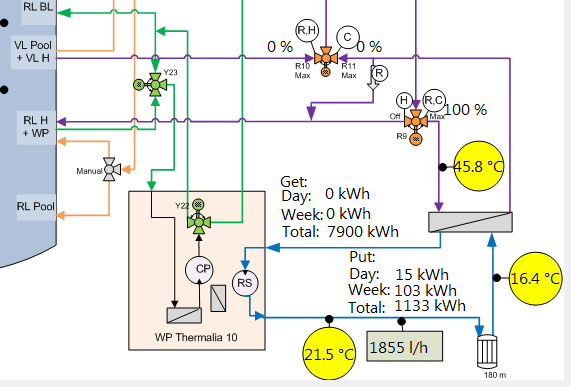
Solar Buffer Cooling
💡 There is ‘live’ status of the system available here. Still experimental, and the ftp upload does not work all the time.
From the solar system I have a peak energy flow of 30 kW. But as I can use the night-time with lower energy costs, I easily can get the energy down into the geothermal system. With an investment of 50 Watts for controller an pumps, I can pump 10 kW of energy into the ground :-). Because of lower temperature, the floor cooling is not as good as this, but still 1.5 kW. But this is not that big of a problem: the floors are very inert, and it is know in advance if there is a heat wave coming. So I can cool slowly down in the nights before, getting me a comfortable house temperature.
Summary
The system is still experimental, but works very well so far. I’m able to cool about 1.5 kW from the floor system, and about 10 kW from the buffer. The pumps and electronics need around 50 W, so not bad compared to a traditional air conditioning system :-). Additionally, I can regenerate the geothermal system during summer time to get a better delta temperature during winter time, which should improve the overall system performance. In retrospect, I should have selected a larger heat exchanger, just to get energy transmitted more efficiently. What surprised me is the heat pump vendors do not consider to use the geothermal system for cooling. It exists for industrial systems, but somehow they do not realize that with little effort and investment the comfort and usability of a system can be greatly enhanced. Especially a joint geothermal+solar system sounds ideal to me for such an application. To make it work, I had to build my controller and heat pump hack based on the FRDM-KL25Z. Another ‘cool’ usage of the Freedom board in my view :mrgreen:.
Happy cooling 🙂

Fascinating. Loved every part of it, even the geologic history, and especially all the photos.
Thanks for sharing so much
LikeLike
You are welcome 🙂
I still need to work on the ‘publish data to the web part’, you might have a look here: http://www.solar.steinerberg.com/
There is still a problem that data does not get pushed regularily to the site, it is still experimental.
LikeLike
Cool! 🙂
I have been thinking about these underground heat deposits for a long time. In fact you can also store “cold”.
What I am not sure about is the capacity of the underground well to store/release heat.
How much heat is it able to absorb? How much of the heat you put can you retrieve later? Or will it be dissipated/lost to the adjacent layers?
If the heat is not dissipated quick enough the system “saturates” and it will not be able to absorb heat after some point. On the other hand if it dissipates the heat further from the well, will you be able to retrieve it back? What is the theoretical capacity for your well?
In Bucharest we experience every year at least 3 weeks of continuous 40-43 degrees.
Also the cost of this installation is of importance.
Greetings
Cristian
LikeLike
Hi Cristian,
yes, I know the heat waves in Bucharest very well too :-). About the underground capacity: well, that’s why I count that thing as ‘experimental’ and ‘subject of research’. The stone layers are very different, and some seemed to carry water. At least this was the indication during drilling. If they carry water (and that water typically is flowing), then the energy put down will simply flushed away. Which is good for getting rid of energy and good as well for getting energy during winter time, but bad if it shall be used as a deposit. I retrieved 7900 kWh of energy during last winter. At the beginning, the temperature was 12.5° C, and while it was dropping down to 2.5°C at times when I needed most of energy, it regenerated back to 12° C after a few weeks when I stopped pulling out energy. This tells me that either energy is easily flowing to the drilling hole, or the system is pretty good with recovering. The drilling hole dimension is for getting out as much as 14400 kWh per year, so I only used half of the capacity :-). On the other side as of today I pulled down 1671 kWh of heat, so I have not put down yet more than I have got out. Will see how this goes.
Cost of installation is a valid concern. But I needed anyway a new heating system. Just looking at the costs for the cooling part: this is in the range of CHF 200.–, not counting my work time of course :-). A usual air conditioning system would cost at least CHF 1000.–, and would burn much more energy. Calculating in the electricity needed for such an air conditioning system, at least the added hardware will pay off during one summer already.
So I continue to measure the data (that’s why I have an additional data logger installed measuring temperature, flow and pressure). Will see how this goes…
LikeLike
Erich, Very cool! (we’ve been close to 37C here this week, aircon running “full tilt”)
Your old heating plant components look like brand new!
I was wondering, the heat exchanger tubing that go into the ground, it came on a big coil, so I assume it is made out of some kind of plastic? Is that a special material with high thermal conductivity? Or is that attribute not required?
The redish brown piping with all the valves, etc. Is that painted threaded steel pipe?
It looks like you have enough plumbing and gadgets in there to run a nuclear power plant. 🙂
I looked on Google and learned in “.ch” you get a lot of your electric power from nuclear and renewable. Here locally I think ours comes from burning coal and oil. A few people have started installing solar panels on the roof to generate electricity. That is still very expensive.
You mentioned a normal air conditioning system would cost at least CHF 1000. According to Google that’s about US $1000. That’s cheap! (ignoring the energy used) You wouldn’t get much of an air conditioning system here in USA for $1000, that’s for sure.
Bill
LikeLike
Hi Bill,
The Swiss energy mix is around 60% hydropower, around 40% is nuclear power, plus some small percentage solar/wind/thermal energy (http://en.wikipedia.org/wiki/Energy_in_Switzerland). Having said that: the country plans to phase out the nuclear power option in the next 20 years (http://en.wikipedia.org/wiki/Nuclear_power_phase-out#Switzerland).
Yes, the exchanger tubing is made of PE plastic. PE already has good thermal characteristics. And no, I cannot run a nuclear power plant with all my plumbing ;-). As for solar panels: there is goverment funding plan which compensates the additional costs of solar energy, and there is huge waiting list for this. Installing solar panels on the roof is getting more and more popular as the panel prices dropped dramatically last year. Now you get 200 Wp (Watt peak) for less than around $300 (you need to add the installation/etc). Compared to around $1000 for the same a couple of years ago, this is not bad. With this you can produce solar electricity for around 25 cents per kWh, still twice the price you get it otherwise.
The price for such an air conditioning is not for a system you have in the US (for the whole house). I’m talking here about a 2000 Watt system like this one (http://www.amazon.de/exec/obidos/ASIN/B000KPQHNE/testberichte_sub1-21/ref=nosim&ascsubtag=3702_242726_51eae5de_51eae5dd). You probably would need one of these for each room I guess. But this is what you might install as buildings typically have no AC system installed at all.
Erich
LikeLike
Pingback: Beating the heat with geothermal cooling
this is amazing,
from concept to execution, the live web interface seems to be working and i cant wait to see what kind of practical performance you get out of the system in the long run, very interesting.
how fast a response time do you have on a system like this?
is the heat delivery instant to the house when needed or is it dependent on a managed steady state to maintain temperature? (i guess this depends on the heat pump)
LikeLike
Thanks for reading. The system does not need to react fast for heating: the warm water boiler is inside the water tank and rather large, so it buffers for a good time. Cooling is slower, due the smaller temperature difference (a delta-T of about 5 degree), as it is ‘free flowing’ and not using active cooling. But uses less energy that way. I have it ‘human predictable’: if the weather forecast is showing a heat wave in advance, I’m cooling down with the FRDM-KL25Z during the night hours in advance, as the floors react slowly too (mass of building). Bottom line: heating is not a problem at all, cooling needs to have predictive control.
LikeLike
Hi from Romania(again)! Although i live in a cold region, in the center of the country, sometimes the temperature is over 30 degrees Celsius, which is unacceptable. I was thinking of running, during hot days, a freezer compressor, which would cool a liquid and push it trough my radiators. With this solution I would avoid drafts and noise caused by AC, and also i would be able to ventilate the rooms without losing too much energy. The thing I wonder about is condensation, people have been warning me about it. To avoid it, should I keep the temp difference small? if so, how small?
Konstantin
LikeLike
Hi Konstantin,
Such an active cooling very likely is subject of condensation, and problematic. The condensation depends on the surface temperature (what you are cooling) and the humidity of the air, in combination with the temperature. See http://en.wikipedia.org/wiki/Dew_point
LikeLike
Pingback: Aquecimento e arrefecimento geotermal | Novidades no Front
Great system, terrific writeup. In your writeup, just drop the “kW per hour”; it is just kW (or kWh per hour ;). Have you considered using an svg-type graph rather than png for displaying info? You don’t generate a new picture, but just replace the numbers…
LikeLike
Thanks for that hint, I have it fixed now. For the display I have considered such an option, but not implemented yet. As said, it is still experimental, and image upload by ftp is with an old laptop in between which generates that .jpg file.
LikeLike
Beautiful article, thanks for taking the time to write it.
LikeLike
Nice one! Do you have some rough details about the budget needed? Great project!!
LikeLike
That depends on your local supplier and underground characteristics. You can get heat pumps for about CHF 5K-6K, and geothermal installation is about CHF 50 per meter. My calculation was that with the current oil pricing it pays off after about 8 years.
LikeLike
Brilliant. 8 years sound very reasonable. Cool project and fantastic description.
LikeLike
And of course oil prices are going nowhere but up!
LikeLike
That’s a really cool project and an excellent write up! I also live in Switzerland (Vaud/Waadt), it’s great to see some actual hacking going on 😀
Seeing as you look like you’re of the geeky kind, I think you should check out if there are any hackerspaces nearby you (hackerspaces.ch) with like minded people. I’m sure others will be interested in doing something similar!
LikeLike
Hi Sasha,
thanks for the link to hackerspaces.ch. I see that it lists already the Fablab in Horw/Lucerne: 10 meters away from office 🙂
LikeLike
nice…
Only thing you may need is a way to dump heat if you over saturate (external radiator?). But it sounds like you have it under control. Maybe a high med low band warning system and have it email/sms you?
LikeLike
Yes, it automatically dumps heat with an external radiator. It is installed in the schematics just after the hot output of the solar panels. It is able to dump the heat before getting into the buffer, typically drops the fluid temperture by 10-15 degree. Dumping the heat is performed automatically by the controller if the fluid heat of the panels exceed a configurable limit (with hysteresis, of course). Additionally with the controller I can cool down the system over night with putting it in ‘reverse’ mode: the buffer heats up the panels overnight to get rid of heat. If this all is not enough, the system is having a passive drain back implemented: with this, the panels get emptied and the fluid is placed in 5 barrels (you see them on the picture of the solar panels) (I call the barrels ‘beer barrels’ as they look alike 🙂 )
LikeLike
Isn’t that a giant overdo, as a simple awning over the solar panels would do? I wouldn’t want to touch those kegs when they just filled 😎 The need for dumping by the way supports my idea to go geo & ‘all electric’ on heating; PV panels never dump. I’m about to calculate my energy losses due to dumping. That is, 3m2 is casting shadow on PV loss + ‘never used this solar heat’ loss + 3m2-could-have-been-PV loss…
LikeLike
Yes, I have the ability to cover the solar panels too. I did that last summer. But this was manual, and I experimented with covering 50% or 80% of the panels. This worked very well, and would be prefered (“not to collect engergy if you want to get rid of it”). Ideally that cover would be automatic too, but it is simply not the case. Plus it would not stand a thunder storm we have frequently during summer time too. PV panels are great (I have some installed too, btw). You get around 20% efficiency from the PV, while I get 80% from the solar panels. I would need a lot more panels to heat the electrical way. Solar heat is ‘low energy heat’ and good for warm water/heating and very efficient. In my view heating with electricity is wasting ‘high quality energy’ ;-). For this, pure electrical heating is not allowed in many areas, including mine (or subject of a lot of regulation).
LikeLike
Ha, that was my concern too. However: 20% efficiency of PV that drives a heat pump with a COP of 5 yields 5 kWh per kWh of electricity. That is 100%, which is better than 80% in (your) PT. When using (ultra) low temperature hydronic heating, the COP will be better than 5, working even more toward PV+heatpump being a winner. PLUS the already mentioned benefit of never going into stagnation (but feeding the electricity to the net, for use in aircos of poor sods not having ground loops 🙂 Running the water through an outside radiator would then regenerate the ground loop in warmer periods (when the cold is not needed for hydronic airco).
LikeLike
Yes, exactly, that’s why I have installed a PV too: I’m feeding the additional electricity into the net. With the current combination, I get all the needed warm water for cleaning/washing/showers from end of March to beginning of November, and do not need to run the heat pump at all to generate heat. It us used during summertime in a passive way to warm up the underground, and as you say to improve the COP to hopefully more than 5 (still subject of measurment over a longer time period). At least in last winter the solar panels were covering my warm water needs for 40% (but it was a ‘dark’ and cold winter).
LikeLike
With all that plumbing and those barrels you could start making Doppelbock! 🙂
LikeLike
Yeah, that would be my next project 🙂
LikeLike
I saw similar system being installed on a TV show, in USA. They used one of these steerable horizontal drilling machines used a lot to put wiring and conduits underground. Gadget seen a lot around here made by Vermeer. They claimed it went down about 10′ deep. They “pulled” the heat exchanger pipes back into the hole with a big winch. About 200′ of the piping. Doubled like yours is. The property had plenty of lawn area doing nothing where they could put the pipe.
LikeLike
Yes, I have seen a similar system here. They are using these kind of horizontal drilling for properties where they cannot drill deep enough because of the presence of sensible underground fresh water, or where there are special underground clay layers which act as a barrier. As the individual pipes are rather short, I have seen systems using CO2 (instead of water with glycol) as fluid: CO2 will be cooled down to the liquid level, then it flows into the pipes. It will evaporate and with this takes out the heat. Very neat system as basically does not require a pump to get the fluid flowing. This kind of system get used more and more in Germany I was told. The drawback is that you cannot use plastic pipes: you need special metal pipes. The welding is an issue for longer pipes, but if you have shorter (say 10 meter or so) pipes, you can get the pipes in one piece, thus very attractive for this kind of system.
LikeLike
Very useful post. I really like it. Thanks for sharing.
LikeLike
Pingback: Snow on Green | MCU on Eclipse
Thank you for sharing this excellent description of a real-live project. Your system looks beautiful. I will use your writeup to help explain the Geothermal system to my colleagues at the Powell River Academy of Music. We are looking at replacement of the gas fired boiler for our school. Our current gas costs are just over $30,000cdn per year. We hope to attract Government money to assist our project, as a demonstration for other schools. Thank you for preparing this excellent description of your project
Jim Donnelly
Powell River B C Canada
lassinantti@gmail.com
LikeLike
Hi Jim,
I wish you sucess with that! My system now runs for more than one year, and I’m very happy about it 🙂
LikeLike
Pingback: Lakeside View | MCU on Eclipse
Hello, I’ve a system like that only with the free cooling. But I don’t remember how to change the reference for the temperature that enter into the floor distribution.
I’ve also a Toptronic T
Best regards
Olivier
LikeLike
I have added for this a dedicated thermostat which controls a valve. That system is worth gold during the current heat wave 🙂
LikeLike