Sometimes it takes a while until things get better. Same thing applies to software: from time to time a refactoring and simplification makes sense. Especially if the underlying technology has been improved. With CodeWarrior for MCU10.3 available, it is time to refactor the LED component.
The ‘old’ way using GPIO_LDD
In my tutorial about using LED’s with the Freedom board, I showed how to use an LED component. For this, I used GPIO_LDD as this was the only way possible at this time:

Using GPIO_LDD
GPIO_LDD is rather complex to set up. Even more, it was not possible to use a single interface for my LED. I had to add a dual interface. The connection from the LED component to the GPIO_LDD was done with special settings in the LED component properties:

GPIO_LDD Connection
So for ARM/Kinetis, it was using a LDD interface, where it was using BitIO for every other architecture. BitIO is using BitIO_LDD
The new way: BitIO is using BitIO_LDD
With the availability of CodeWarrior for MCU10.3, things finally have been improved: it is possible to use BitIO_LDD :-). CodeWarrior for MCU10.3 supports now the earlier BitIO component, and interfaces it automatically with the BitIO_LDD sub-component. With this, it is possible that I get rid of my LDD interface :-). Which makes everything easier to use.
Migrating to the new component
Unfortunately I have not found a good way to make things backward compatible. This means if you use that new LED component V1.047 or later, you need to configure it for the LED used. To transform a project from the ‘old’ the new simplified way, following steps need to be performed:
- Download the new LED component and install it in CodeWarrior/Processor Expert
- Open in CodeWarrior the project. The LED’s will show errors as not configured properly yet.
- Remove the GPIO_LDD’s used for the LEDs
- For each LED, configure the LED pin according to the pin connection:
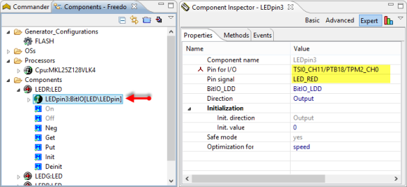
Configuring LED Pin

What happens is that for each LED, the BitIO sub-component will automatically add and configure a BitIO_LDD component:

BitIO_LDD Component
💡 Creating new projects will automatically use the new LED interface, so no extra step is needed.
Summary
Although things are not backward compatible, the usage of the new LED component is now simpler with the usage of BitIO_LDD. The new LED component is available here. I have updated the Freedom Board example projects too.
Happy LEDing 🙂

I would love to see a component such as this one but integrated to timers, so that I could easily get a dimming output on my LEDs.
LikeLike
Let me see what I can do for you :-). With PWM or with normal BitIO toggling?
LikeLike
Here you go: https://mcuoneclipse.com/2012/12/29/pwm-and-shell-for-a-led/
You even get a command line interface now 🙂
LikeLike
Pingback: PWM and Shell for a LED | MCU on Eclipse
how to set Freedom Board with Linux ( Including GDB and GCC) .
LikeLike
Sorry, I only used Windows. You might have a look at coocox.org for Linux support.
LikeLike
Pingback: Back to Basic(s) with the Freedom Board | MCU on Eclipse
Hi Erich,
I am not able to compile the generated inline assembly code by using either GCC or ARM compilers. Is there anything I need to do to make my code compile?
For example, this piece of code, which simply waits for 10 CPU cycles,
/* This function will wait 10 CPU cycles (including call overhead). */
asm {
/* NOTE: this is not really accurate, as not sure yet about the cycle counts */
nop /* assuming one cycle for nop */
nop /* assuming one cycle for nop */
nop /* assuming one cycle for nop */
nop /* assuming one cycle for nop */
nop /* assuming one cycle for nop */
nop /* assuming one cycle for nop */
nop /* assuming one cycle for nop */
nop /* assuming one cycle for nop */
nop /* assuming one cycle for nop */
nop /* assuming one cycle for nop */
}
ARM compiler complains
./Generated_Code/WAIT1.c(51): error: #20: identifier “asm” is undefined
While GCC compiler complains
./Generated_Code/WAIT1.c(51): error: expected ‘(‘ before ‘{‘ token
./Generated_Code/WAIT1.c(53): error: unknown type name ‘nop’
./Generated_Code/WAIT1.c(55): error: expected ‘=’, ‘,’, ‘;’, ‘asm’ or ‘__attribute__’ before ‘nop’
And this piece of code
__asm void Cpu_EnterCritical(volatile uint8_t *SR_reg) {
PUSH {R0,R1}
MRS R1, PRIMASK
CPSID i
STRB R1, [R0]
POP {R0,R1}
BX LR
ALIGN 4
}
gives this error in GCC compiler
./Generated_Code/Cpu.c(132): error: expected ‘(‘ before ‘void’
ARM compiler didn’t complain anything, but it might just be that it halted before it.
Thanks a lot!
LikeLike
Hello,
are you using the Wait component from the GitHub on https://github.com/ErichStyger/mcuoneclipse?
this one definitely supports ARM gcc.
And: can you verify that the compiler is set to Gcc in the Processor Expert CPU componen settings (build options tab)?
LikeLike
Thanks Erich, it works after setting the build options. 🙂
LikeLike
Good to hear that things are working now :-). But I’m wondering why you had this problem, because CodeWarrior automatically sets the correct compiler. Do you know why you had a wrong setting?
LikeLike
I am not actually using Code Warrior (because I don’t have its license). I am just using the stand alone processor expert software to generate code, convert that into a Keil Microvision project and compile/debug it there. I didn’t realize that by default the code is generated in Code Warrior syntax.
By the way, what other compilers do you support, other than the CW compiler and GNU compiler?
LikeLike
You do not need a CodeWarrior license: without a license, it is limited to 64 KByte code size for Kinetis-L which is a lot. Other CPUs have even a 128 KByte limit, so plenty of room to do development free of charge.
And I support right now IAR, CW and GCC compiler syntax. As long as it is ‘C’, no issue with other compilers. But of course the assembly language syntax is many times different for different compilers (like in the WAIT module).
LikeLike
Pingback: Tutorial: Enlightning the Freedom KL25Z Board | MCU on Eclipse
Pingback: Using the FRDM-KL25Z as USB Keyboard | MCU on Eclipse
Pingback: Tutorial: Ultra Low Cost 2.4 GHz Wireless Transceiver with the FRDM Board | MCU on Eclipse
Pingback: First Steps with the Freescale TWR-K64F120M | MCU on Eclipse
Hello, Erich.
First of all, congratulations by the excelent content in your page!
I’m a embedded software student and developer, and now I’m really searching, and (trying) to develop for freescale architeture.
I have a simple doubt, and I hope that you can help me in. hehe
I do not want to use Processor Expert in my projects., but I’m encountering a lot of obstacles in web to find some examples and applications that do not use PE. I’m simple trying to set a port to output for my K22F board, but without PE is being a hard task.
I searched in the .c and .h files using PE to find the registers call and how I can call an output pin.
I tryed PTADD_PTAD1, PORTA_PORTAD1, PORTA_PTA1… And nothing worked for me.
Please, can you explain to me how can I call a pin by output, and how can I set it in High Logic Level (an in board Led, in the case).
I really appreciate your help.
Thanks in advance.
LikeLike
Hi Guilherme,
well, you want to have things easy and simple to use, then really I recommend using Processor Expert. That’s why it is there and that’s why I use it: because it makes these kind of questions obsolete and you do not have such kind of problems :-). Sure you can do things any other way too, but it takes a lot more work and learning. I recommend that you create a project with the SDK enabled for the K22F board with the new project wizard in Kinetis Design Studio: there you can have the Processor Expert option disabled. The SDK comes with HAL (Hardware Abstraction Layer) and CMSIS compliant header files, so you can use those to interface to your LEDs. I hope this helps.
LikeLike
Hi, Erich.
Thanks for the fast answer. I need to implement and acquire data from the acelerometer in the board, write its data in EEPROM, use 2 threads to do the control software and send the data with USB to a terminal. hehe
I did develop a lot using PIC, AVR, Arduino IDEs and MSPs.
But… I like the old way to program using registers and low level software. hehe
I understand that P.E. is really nice by its simple implementation, but I’m resistent about its time to process and the freedom to optimize and work into the functions. Maybe my fear is fool. hehe
And searching in the web, all people use it, so… its probably that I’m wrong about P.E..
Well… I think that I’ll try to use it, check its performance and see by my own eyes. hehe
Your site is really awesome, and you do a lot of things using freescale uc. I’ll use it to read about some communication protocols and take out some doubts, my friend. hehe
Thanks a lot by the answer, and keep doing the awesome job with the page.
Regards!
LikeLike
can give me sample code for this LED compenent. and i cant use “wait” component because appear when was used “Description Resource Path Location Type
ERROR: at line 10: Property not found: “LDDWatchDogEnabled” (file: Beans\Wait\Wait.chg) cobajlink WAIT1 Processor Expert Problem
“
LikeLike
Hello,
it looks like something is wrong with your component. Have you installed the latest version from SourceForge (https://sourceforge.net/projects/mcuoneclipse/files/PEx%20Components/) already?
LikeLike
VERY COOL! Using the uTasker project has been on my list for a very long time, so now I guess there is no lame excuse possible any more ;-). And I’ll make sure you get a board (or more) 🙂
LikeLike
Are there any tutorials out there that don’t involve CodeWarrior? I can’t afford it and everything I have seen on Google uses CodeWarrior.
LikeLike
Hi Ed,
I have pretty much moved over to standard Eclipse and Kinetis Design Studio (with the the GNU ARM Eclipse plugins). Actually this tutorial applies pretty much to Kinetis Design Studio too. That’s the beauty with Processor Expert: it is the same on different Eclipse distributions.
Does this help?
LikeLike