I have not received my pre-ordered boards yet, but at least I have now one of the new black ones, see this post. And I have good and bad news.
Pre-Ordered Boards
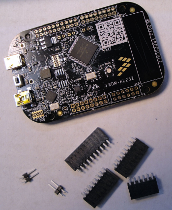
Good news: A reader of this blog has sent me pictures of his board he received yesterday:
The good news is: the Arduino headers on the side plus the two jumper headers were shipped in a plastic bag. Well, will see what I will get ;-).
The bad news: no battery holder, and no serial Flash chip :-(.
Arduino Shields
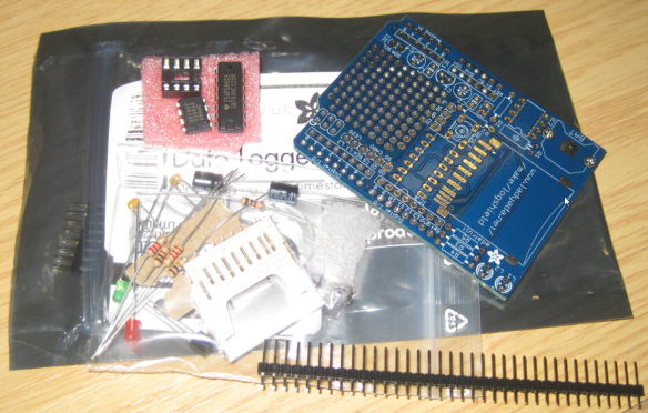
The good news is: My Adafruit Data Logger Arduino Shield arrived. This is a ‘solder yourself’ kit:
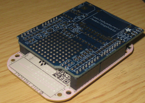
And the shield nicely fits to the form factor of the Freedom board:
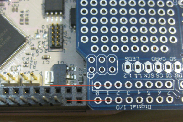
The bad news is: the headers do not fit :-(. The header row pitch on the Arduino is kind of non-standard, not matching the Freedom board header:
I’m not very familiar why the Arduino board header is that strange, but I would have expected that the Freedom board would match with it? At least this does not make much sense to me.
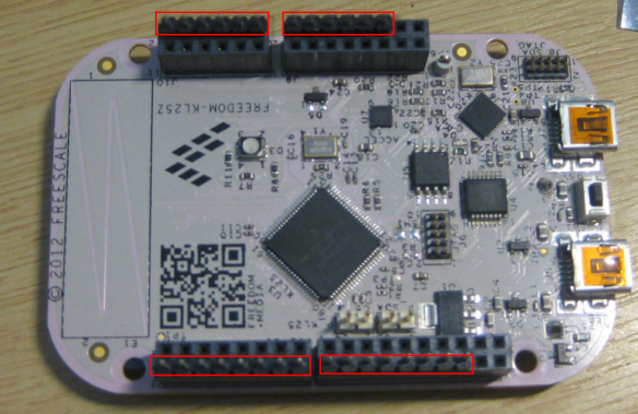
So what I end up is that I only can use the outer rows of the header. What I can use are the ones marked in red:
So I’m glad that I have an ordered an Arduino Shield board which I can solder myself, otherwise the board would have been quite useless :-(. I might even think about the need to create an adapter board between Freedom and Arduiono? I doubt that this was the idea of the Freedom board, and maybe I just have ordered a wrong Arduino Shield board.
In case this helps anyone: I have not found any drawings of the Freedom board, but a reader has forwarded me a link of Arduino drawings.
Unhappy Headering 😦

Hi, Eric,
The Arduino R3 pin layout standard specifies a single row or 100mil spaced IO headers. The KL25Z in an 80LQFP package has many extra IO pins that are brought to an inner row. I’m not sure what the inner row on the ada fruit data logger is, but it obviously isn’t 100mil spaced from the outer rows. Are there signals on those pins?
The possible interference with Arduino shields is one reason why we didn’t populate the headers on the FRDM-KL25Z. User’s are able to populate with 1xN connectors on the outer row and leave the inner row unpopulated if desired or needed.
-Michael
LikeLike
Hi Michael, the Adafruit Arduino shield has the same signal on both the inner and outer row (for most pins). Means they are mirrored to the ‘inner’ row.
Not sure if this is the case for many Arduino boards.
What I see from the picture from a user is that Element14 ships two-row headers. So if I would have populated it, and would populated the Data Logger shield, I would have a problem. So it looks to me that I better carefully make sure what I populate and what not, because otherwise I might have a conflict.
I see other boards have two rows as well, e.g. http://www.adafruit.com/products/802. But it looks like the second row is used kind of additional signal source, but not intended to be connected to the lower board. With having the Freedom board two rows too, I was assuming that it is intended that both get connected. Obviously not the case, so my wrong thinking.
LikeLike
Just a note on the mirrored “inner” rows on your adafruit board: I think you’ll find that most boards with prototype space do this to provide somewhere to solder wires to bring the corresponding signal into the prototype space.
LikeLike
yes, indeed. I see this on several boards as a way how to stack up boards and route the signals to the other board. They serve as good test points as well.
LikeLike
Looks like non-preordered boards (ordered Sept 6th at Newark (US Farnell), and it arrived this Friday) don’t include headers anymore, not on the board and not in a bag. I see there are only two sets of pins included for jumpers in that photo, and it looks like the white prototype boards also only had 2 jumpers in place, but my board has 3 sets of jumper holes (J3, J4, and J11), does anyone know what the new J11 is for? I guess I need to order some double row female headers at some point, and probably some 1.28mm headers too. But that doesn’t stop me from playing with everything onboard in the meantime and your blog is a huge help there!
I’m not sure what’s up with the second “inside” set of arduino-style headers on that shield. Sometimes with shields you’ll see a second set of holes for headers offset from the first so you can stick male pins in one pointing down and female in the other pointing up and not have to buy the expensive “stacking” female headers with long male pins. The downside being increasing the size of the PCB beyond the bare minimum required for a shield and also creating a staircase effect if very many are stacked at a time.
But on those adafruit shields the other set aren’t offset to preserve the spacing, they’re closer together. Maybe it’s just so you can still have easy access to plug wires into the Arduino’s pins when working with a breadboard?
Something else to watch out for on Arduino headers is the mistake on spacing between what are the J1 and J2 headers on the Freedom board — it’s not a 0.1″/2.54mm-multiple gap between the two, but 4.06mm. The freedom board looks like it gets this right for Arduino compatibility, though of course that means it’s a pain for stuff like building a shield on protoboard or any other sort of 0.1″ grid. Legend has it that it was a mistake made by a slip of the mouse in the last few minutes before sending the first commercial Arduino board off to be manufactured, and the prospect of fixing it and breaking compatibility with the growing ecosystem of shields just gets harder and harder every year.
LikeLike
Yes, I have seen other comments on Element14 which indicate that the headers are only delivered with pre-ordered boards, and do not come with the ‘normal’ production boards.
About J11: I have not found it in the schematics, but it is described in the User Manual available on Element14 site:
“Signals with SPI and GPIO capability are used to connect directly to the SWD of the KL25Z. These signals are also brought out to a standard 10-pin (0.05”) Cortex Debug connector (J6). It is possible to isolate the KL25Z MCU from the OpenSDA circuit and use J6 to connect to an off-board MCU. To accomplish this, cut the trace on the bottom side of the PCB that connects J11 pin 1 to J11 pin 2. This will disconnect the SWD_CLK pin to the KL25Z so that it will not interfere with the communications to an off-board MCU connected to J6.”
For the ‘inside’ header pins: yes, I think I will need an adapter board to use them, only most of the ‘outer’ pins are available with standard shields (see comment from Michael Norman). And yes, I see that the second row of pins on the normal shields is used for stacking boards (with a ‘staircase effect’.
And thanks for the story behind the spacing between J1 and J2. It sounds funny :-), but I believe this really is probably the root of that odd thing.
LikeLike
My pre-ordered boards arrived today from Farnell Switzerland. But no headers included 😦
LikeLike
What applications would benefit from the missing 16Mbit flash chip if one were to add it to the KL25Z production version? Bearing in mind that the M0+ has no floating point accelerator.
ATMEL AT45DB161D-SU IC, FLASH, 16MB, SOIC-8; Memory Type:Flash; Memory Size:16Mbit; IC Interface Type:Serial, RapidS; Clock Frequency:66MHz; Supply Voltage Range:2.7V to 3.6V; Memory Case Style:SOIC; No. of Pins:8 ;RoHS Compliant: Yes
LikeLike
Unfortunately that serial flash is *not* connected to the KL25Z. It is connected to the K20 OpenSDA debug chip on the board. There are no details or sources of the OpenSDA available, but I would envision it could be useful for the OpenSDA debug application to use that storage for storing trace information or monitor variable changes over time, and then report to the debugger. The other thinking is that I could wire the pins of the serial flash to the Arduino header rows, giving me access to the serial flash from the KL25Z. I still not have made up my mind, but I likely want to run FatFS file system on the chip so the device could store files/etc on the flash.
LikeLike
Thanks for that info. I was going to buy some AT45DB161D-SU from Newark but now am not so sure if I will.
LikeLike
Pingback: Tutorial: printf() and “Hello World!” with the Freedom KL25Z Board | MCU on Eclipse
Pingback: Completing the FRDM-KL25Z Board | MCU on Eclipse
Pingback: Arduino Data-Logger Shield with the FRDM-KL25Z Board | MCU on Eclipse
Pingback: Processor Expert Maxim I2C RTC Driver the Arduino Data Logger Shield | MCU on Eclipse
Pingback: First Steps with Avnet’s Wi-Go Board | MCU on Eclipse